Model XE569s
Work
Disassembling and assembling
of parts
Parts
11.
Inclinable
Rail
Assembly
Ver.
1
2
3
4
Steps
1. Follow
the
procedure
10
to
rem
ove
the
rail base
assem
bly.
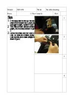
2.
Use Phillips head screwdriver to release
M5x15mm
phillips
head
screws
which
secure
the
rear bar cover,inclinable rail cover and
incline
cover, as
shown
in
figures
1&2&3.
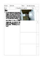
3. Use two 14 m
/m
wrenches to release
3/8
"x2-1/2"
hex
head
bolt,
3/8
"x19x1.5T
flat washer and 3/8
"x7T nyloc nut which
secure the inclinable rail assembly and
incline motor holder, as shown figure 4.
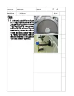
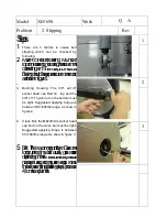
4.
Use 12 m
/m
wrench to release 5/16"x1
hex
head
bolts
and
5/16
"x35x2T
flat
washers
which secure the inclinable rail assem
bly.
Pull out the locking tube assem
bly and the
inclinable
rail assem
bly can
be
taken
apart, as
shown
in
figure
5.


