background image

3  USER INSTRUCTIONS


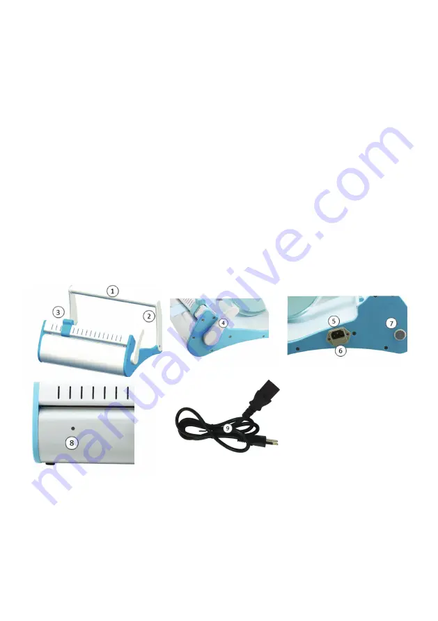
1 -  Mount the Holder support (see fig 1)  to the chassis.

2 -  Connect the power cord to the power connector which is on the left side of the sealer, 

check if the voltage of your equipment matches the voltage of the local electrical network.

2 -  Switch the sealer on by using the power switch on its left side. When the green LED goes 

on (after around 3-5 minutes) the sealer will be ready to be used.

3 -  Place  the  roll  on  the  holder.  The  beginning  of  the  roll  shall  be  inserted  through  the 

back side, between the pressure bar and the sealing bar always with the paper side down 

(resistance’s) side and the plastic side up (directly under the upper pressure bar).  Push the 

sealer arm (4) towards Paper Holder (1)  and press it down softly until it is locked.

4 -  When the GREENled turn to RED the sealing will be completed. An acoustic signal will 

be emitted to inform that the seal is ready. 

5 -  Leaving the Sealer Arm pressed cut the envelope sliding the blade (3). Raise the sealer 

arm and remove the envelope. If the Sealer Arm is left in “sealing” position for a longer time 

the RED light will start to blink and another acoustic signal will be emitted. 

5 -  For the cleaning always use a soft cloth. Never spill or spray liquids directly on the sealer.

6 -  The smell of burnt of the equipment at the first putting into service is a normal situation. 

The smell disappears with the use of the equipment.

4  COMPONENTS DESCRIPTION

5  TECHNICAL DATA

Input 

220 – 240 V AC 

Preheating Time 

Max 5 min

Frequency 

50/60 Hz 

Net weight 

7 kg

Power 

100 W 

Gross weight 

9 kg

Seal width 

12 mm 

Maximum dimension  490 x 390 x 220

Max Seal Length   300 mm 

Fuses 

250VFL8A

Reference standard  IEC 61010-1 /EN 61010-1


IEC 61326-1 / EN62326-1 

5 Leaving the Sealer Arm pressed cut the envelope sliding the blade (3). Raise the sealer arm and remove the envelope. 
If the Sealer Arm is left in “sealing” position for a longer time the RED light will start to blink and another acoustic 
signal will be emitted.  

5 For the cleaning always use a soft cloth. Never spill or spray liquids directly on the sealer; 

6 The smell of burnt of the equipment at the first putting into service is a normal situation. The smell disappears with 
the use of the equipment. 


4


COMPONENTS


DESCRIPTION


1) Paper Holder 

2) Holder support 

3) Blade knob 

4) Sealer Arm 

5) Power Connector 

6) Fuse 

7) Power switch 

8) Indicator 

9) Power chord 

Fig 1) 


5


TECHNICAL


DATA


Input 

220 – 240 V AC 

Preheating Time 

Max 5 min 

Frequency 

50/60 Hz 

Net weight 

7 kg 

Power 

100 W 

Gross weight 

9 kg 

Seal width 

12 mm 

Maximum dimension 

490 x 390 x 220 

Max Seal Length  

300 mm 

Fuses 

250VFL8A 

Reference standard  IEC 61010-1 /EN 61010-1 

IEC 61326-1 / EN62326-1 


Fig 1)

1) Paper Holder

2) Holder support

3) Blade knob

4) Sealer Arm

5) Power Connector

6) Fuse

7) Power switch

8) Indicator

9) Power chord

Summary of Contents for SELLA II

Page 1: ... MANUAL MODE D EMPLOI GEBRAUCHSANLEITUNG MANUAL DE USO AUTOCLAVE 16 lt AUTOCLAVE 16 lt Dispositivo Medico conforme alla direttiva 93 42 CE FARO SPA Ornago Italy 0051 SELLA II MANUAL SEALER SIGILLATRICE INSTRUCTION MANUAL MANUALE D USO ...

Page 2: ... instruments into the autoclave Check the instructions from the manufacturer of your autoclave regarding the arrangement of the packages and the sterilization cycle 5 Risk of electrical shock always unplug the power cord when servicing or cleaning the equipment Service must be performed by qualified personnel 6 Risk of electrical shock do not spray or spill any liquid on the sealer 7 Risk of hot p...

Page 3: ...quipment at the first putting into service is a normal situation The smell disappears with the use of the equipment 4 COMPONENTS DESCRIPTION 5 TECHNICAL DATA Input 220 240 V AC Preheating Time Max 5 min Frequency 50 60 Hz Net weight 7 kg Power 100 W Gross weight 9 kg Seal width 12 mm Maximum dimension 490 x 390 x 220 Max Seal Length 300 mm Fuses 250VFL8A Reference standard IEC 61010 1 EN 61010 1 I...

Page 4: ...ti 4 Rischio di chiusura non efficace posizionare le buste sigillate con gli strumenti in autoclave Verificare le istruzioni del produttore dell autoclave per quanto riguarda la disposizione dei pacchetti il carico massimo ed il ciclo di sterilizzazione 5 Rischio di shock elettrico scollegare sempre il cavo di alimentazione durante la manutenzione o la pulizia dell apparecchio La riparazione deve ...

Page 5: ...rto L inizio del rotolo deve essere inserito attraverso il lato po steriore tra la barra di pressione e la barra saldante sempre con il carta in giù lato resistenza e lato plastica in alto direttamente sotto la barra di pressione superiore Spingere il braccio di sigillante 4 verso il supporto di carta 1 premendolo delicatamente finché non si blocca 4 Quando il LED verde diventa rosso la tenuta sar...

Page 6: ...trica 6 Portafusibile 7 Interruttore di acensione 8 Indicatore di stato 9 Cavo di alimentazione Fig 1 7 DATI TECNICI Input 220 240 V AC Tempo di preriscaldo Max 5 min Frequenza 50 60 Hz Peso netto 7 kg Potenza 100 W Peso lordo 9 kg Altezzasigillo 12 mm Dimensioneimballo 490 x 390 x 220 Lunghezzasigillo 300 mm Fusibili 250VFL8A Standard internazionali IEC 61010 1 EN 61010 1 IEC 61326 1 EN62326 1 1 ...

Page 7: ...cattiva manutenzione o di normale usura I CERTIFICATO DI GARANZIA GB GUARANTEE CERTIFICATE Faro offers the final customer a 12 month guarantee starting from the date of purchase Repairs under guarantee must be performed at FARO expenses and transport risks are at the risk of the purchaser Repair under guarantee is considered valid only when all sections of the certificate have been filled in and s...

Page 8: ...ED 0 1 COD 988222_REV 00 Sigillatrice SELLA II GUARANTEE CERTIFICATE CERTIFICATO DI GARANZIA 1 4 ...

Reviews: