background image


Page 

10

Figure 1-10 

Figure 1-8 

Figure 1-9 

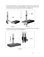
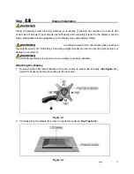
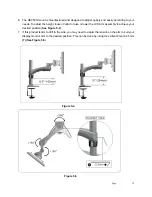
7.  Place the Plastic Gasket Cushions on the metal plate and base as shown (

See Figure 1-8

).  


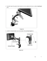
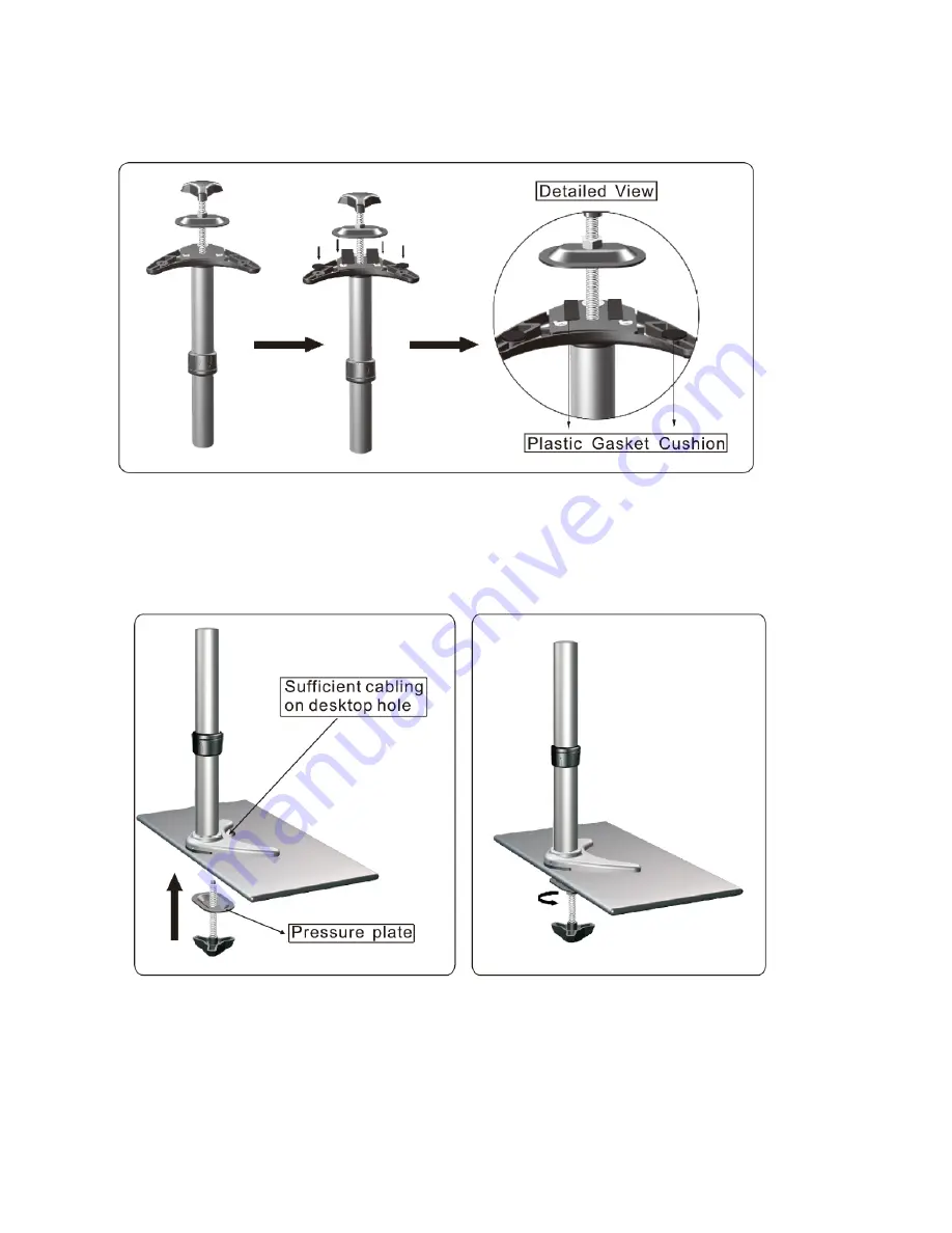
8.  Attach the Grommet Clamp


Pole

 (2)

 to the edge of the desk in the desired position and ensure 

that there is sufficient cabling in the desktop hole as shown (

See Figure 1-9

). 

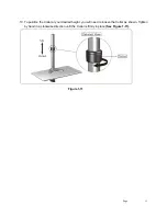
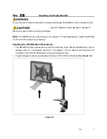
9.  Tighten by hand to ensure that the Grommet Clamp pressure plate is pressed flat onto the desk 

surface and is secure (

See Figure 1-10

). 


Summary of Contents for Butterfly Series

Page 1: ...t ...

Page 2: ...the corresponding instructions It is the installer s responsibility to make sure all components are properly assembled and installed using the instruction manual provided Using improper screws or screw size may damage your display If spacers are required be sure to use screws of the correct size Proper screws will easily and completely thread into the display mounting holes Inadequate thread engag...

Page 3: ...ment and pitch roll requirements z This product contains small items please keep these items away from children z Do not exceed the maximum weight capacity for this product Exceeding the weight capacity can result in serious personal injury or damage to equipment Specifications Weight Capacity 17 6lbs 8kg Suits LCD Flat Panel Displays 12 300mm 24 610mm Maximum Extension 11 2 285mm Depth from Pole ...

Page 4: ...Page 4 Product Dimension ...

Page 5: ...Page 5 Supplied Parts ...

Page 6: ...1 Carefully inspect verify that all components are present 2 If the mount components are damaged or missing please contact the company seller of the product you purchased this unit from and report the issue Note Read all assembly instructions before starting the installation process ...

Page 7: ...quired depending on your method of installation Note It is recommended that the DE300S mount be clamped to the side edge or rear of the desktop surface The DE300S mount is suitable for square edged desk only It is the installer s responsibility to make sure the desktop structure to which this product is attached can support the combined weight of all components Installation to Desk 1 Adjust the he...

Page 8: ...dge of desktop See Figure 1 3 Tighten by hand to ensure that the Desk Clamp fully clamps to the desktop surface and is secure See Figure 1 4 4 To position the Collar at your desired height you will need to loosen the Collar as shown Tighten by hand until the Collar is firmly in place See Figure 1 5 Figure 1 3 Figure 1 4 Figure 1 5 ...

Page 9: ...tely thread into the display mounting holes Inadequate thread engagement in the display may cause display to fall Note Other tools may be required depending on your method of installation Installation of Grommet Clamp to Desk 5 Remove the metal plate from DMG 01 See Figure 1 6 6 Attach the metal plate to the base of the pole Thread the Hex Screws M6x8mm into the metal plate using the Allen Wrench ...

Page 10: ...ee Figure 1 8 8 Attach the Grommet Clamp Pole 2 to the edge of the desk in the desired position and ensure that there is sufficient cabling in the desktop hole as shown See Figure 1 9 9 Tighten by hand to ensure that the Grommet Clamp pressure plate is pressed flat onto the desk surface and is secure See Figure 1 10 ...

Page 11: ...ge 11 10 To position the Collar at your desired height you will need to loosen the Collar as shown Tighten by hand in a clockwise direction until the Collar is firmly in place See Figure 1 11 Figure 1 11 ...

Page 12: ... responsibility to make sure the combined weight of all components does not exceed the weight capacity of 17 6lbs 8kg Exceeding weight capacity can result in severe personal injury or damage to equipment The DE300S assembly will only work when a display is properly installed Attaching the Display 1 Ensure that the Tilter Mount Bracket of the arm is able to swivel and tilt easily See Figure 2 1 Adj...

Page 13: ...s with the Spacers 4 Thread the Screws M4x25mm 6 through the Tilter Mount Bracket Spacers and into the display See Figure 2 3 5 Using a Philips Screwdriver tighten the screws so the Tilter Mount Bracket is firmly attached to the display monitor Do not over tighten the screws Stop immediately if you encounter any resistance See Figure 2 4 Note All Spacers or Screws used should be the same length Fi...

Page 14: ...s properly installed Attaching the DE300S Arm Assembly 1 Attach the assembled arm 1 down onto the pole as shown See Figure 3 1 2 Once you have the assembled arm in your desired position tighten the Hex Grub Screw using the Hex Allen Wrench 2 5mm 7 until the arm is firmly in place See Figure 3 2 Figure 3 1 Figure 3 2 ...

Page 15: ...e to equipment Disconnect power before removing the display Note Be sure to leave enough slack in the cables to allow for movement of the arms Installing the Cables 1 Connect cables to the display monitor Fully extend the arm to ensure that there is sufficient cabling at the end of the arms so that the cables are not stretched or pulled out when the display is moved See Figure 4 1 Figure 4 1 ...

Page 16: ...age 16 2 Feed the cables through the cable bracket slot on the underside of the arm as shown See Figure 4 2 3 Attach the Cable Clip 3 to secure the cables to the pole See Figure 4 3 Figure 4 2 Figure 4 3 ...

Page 17: ...s factory set to support 17 6 lbs 8kg displays Adjust the DE300S mount to suit the weight of your displays Adjusting the DE300S Mount Resistance 1 The DE300S mount is engineered to control the resistance in the Tilter Mount Bracket to suit your display swivel of 90 degrees and tilt of 90 degrees You can easily control the amount of resistance in the Tilter Mount Bracket to suit your display monito...

Page 18: ...mm located around the Tilter Mount Bracket Joint using the 4mm Hex Allen Wrench See Figure 5 2 4 To increase or decrease the resistance of the Pivot Joint to suit display monitor swivel adjust the Tension Hex Socket Cap Screw M5x15mm located on the Tilter Mount Bracket Joint to secure the position See Figure 5 3 5 To increase the resistance tighten the M5x15mm Tension Hex Socket Cap Screw using Al...

Page 19: ...osen Collar to raise or lower the LCD Arm assembly to achieve your desired position See Figure 5 4 7 If this product tends to drift to the side you may need to adjust the tension on the arm to suit your display monitor arm to the desired position This can be done by using Hex Allen Wrench 2 5mm 7 See Figure 5 5 Figure 5 4 Figure 5 5 ...

Page 20: ...necessary to prevent repetitive strain injuries which can develop over time and can lead to long term disabilities 1 To ensure the correct focal distance for ultimate visual comfort a viewing distance between 460mm 18 to 610mm 24 is recommended See Figure6 1 Figure 6 1 ...

Page 21: ...pported to decrease disc pressure Sitting in a chair with a backrest that inclines backwards and has adequate lumbar support is critical to prevent excessive lower back pressures The recommended ergonomic seating position to minimize pressures is to sit with the wrists straight at a 90 angle from the floor and seat and knee angle must also be at a 90 angle Angular adjustment to reduce reflection o...

Page 22: ...r visit www dyconn com Dyconn disclaims any liability for modification improper installations or installations over specified weight range Dyconn will not be liable for any damages arising out of the use of or inability to use of Dyconn products Warranty specification is subject to change without prior notice ...

Reviews: