BlueWave® MX-250 Emitter User Guide
7
Mounting/Connections
▪
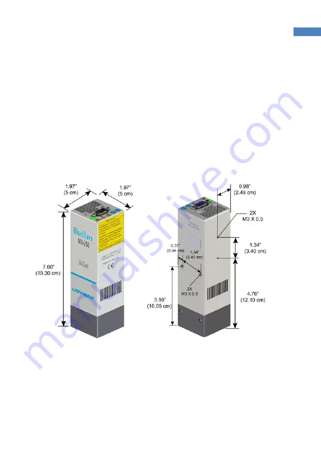
Each emitter has two sets of M3 x 0.5 mm holes (Figure 2) that align with Dymax
stands and holders.
▪
When connecting the emitter to the controller, ensure proper strain relief to
prevent pinching or kinking of the interconnect cable.
▪
The cooling air intake on top of unit must be free flowing, do not cover.
▪
Exhausting air on sides must be given at least 1 mm
(0.04”)
of clear space to
obstructions for safe use.
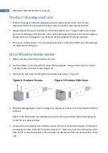
Figure 2. BlueWave® MX-250 Emitter Dimensions
▪
When multiple emitters are mounted side-by-
side, maintain 1 mm (0.04”) of
clear space between uni
ts. For outermost units, maintain 20 mm (0.8”) of free
space to obstructions for safe use.


