background image

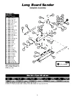
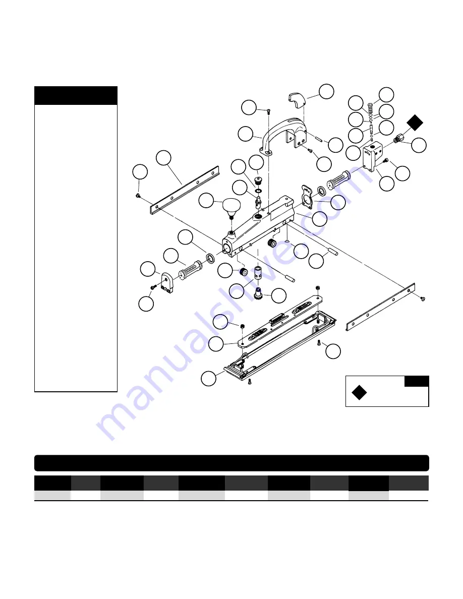
Long Board Sander

Complete Assembly

3

1

06060

Screw (7)

2

06101

Front Cap

3

06062

Piston (2)

4

06064

Piston Ring (2)

5

06071

Gear (2)

6

06076

Valve

7

06077

Actuator Gear

8

06085

Nut (2)

9

06087

Carrier

10

06088

Pad Assembly

11

06098

Screw (2)

12

06072

Gear Shaft (2)

13

06090

Screw (8)

14

06089

Side Strap (2)

15

06067

Knob

16

06075

Adjusting Shaft

17

06074

O-Ring (2)

18

06073

Plunger

19

06080

Handle

20

06081

Screw (2)

21

06082

Trigger

22

06083

Pin

23

06084

Screw (4)

24

06066

Housing

25

06091

Rear Gasket

26

06102

Valve Bushing

27

06103

O-Ring (2)

28

06061

Set Screw

29

06100

Valve Stem

30

06095

O-Ring

31

06096

Spring

32

06092

Rear Cap

33

06099

Inlet Adapter

34

06068

Wear Button (8)

KEY

O

1

O

Oil:

O

1

= Air Lube

1

2

3

9

4

13

14

20

21

19

22

23

27

28

29

31

30

17

26

33

32

1

18

17

24

34

25

16

15

12

11

10

8

5

6

7

Model: 18066

Note:

To order replacement parts

specify the 

Model #

Serial #

and

SPM 

of your air tool.

Index Key

No.   Part #    Description

Machine Specifications

Additional Specifications: Air Inlet Thread 1/4" NPT • Hose I.D. 3/8" (10 mm)
Sound Level is the pressure measurement according to the method outlined in ISO regulation ISO-15744

Model

Motor

Stroke Length

Sound

Max. Air Flow

Air Pressure

Weight

Length

Height

Paper Size

Number

SPM

Inch (mm)

Level

SCFM (LPM)

PSIG (Bars)

Pound (kg)

Inch (mm)

Inch (mm)

Inch

18066

2,500

1 (25)

93 dB(A)

14 (396)

90 (6.2)

5.6 (2.5)

16 (406)

6-1/8 (156)

2-3/4 x 17-1/2

Summary of Contents for 18066

Page 1: ...eral Regulation CFR 29 Part 1910 European Committee for Standards EN Hand Held Non Electric Power Tools Safety Requirements and applicable State and Local Regulations SAVE THIS DOCUMENT EDUCATE ALL PERSONNEL WARNING Some dust created by sanding grinding drilling and other construction activities contain chemicals known to cause cancer birth defects or other reproductive harm Some examples of these...

Page 2: ...ir tool to power source Be careful NOT to depress throttle lever in the process Do not expose air tool to inlet pressure above 90 PSIG or 6 2 Bars Caution After installing the accessory before testing or use and or after reassembling tool the tool must be started at a reduced speed to check for good balance Gradually increase tool speed DO NOT USE if tool vibration is excessive Correct cause and r...

Page 3: ...5 O Ring 31 06096 Spring 32 06092 Rear Cap 33 06099 Inlet Adapter 34 06068 Wear Button 8 KEY O1 O Oil O1 Air Lube 1 2 3 9 4 13 14 20 21 19 22 23 27 28 29 31 30 17 26 33 32 1 18 17 24 34 25 16 15 12 11 10 8 5 6 7 Model 18066 Note To order replacement parts specify the Model Serial and SPM of your air tool Index Key No Part Description Machine Specifications Additional Specifications Air Inlet Threa...

Page 4: ...larly using a strobe tachometer without abrasive accessory attached with 90 PSIG at inlet while tool is running Always check tool speed after any maintenance or repair If tool is operating at a higher SPM speed than marked on the housing or operating improperly the tool must be corrected before use Mineral spirits are recommended when cleaning the tool and parts Do not clean tool or parts with any...

Reviews: