background image

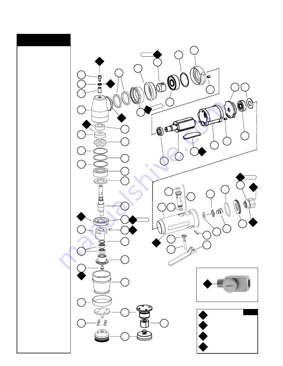
Right Angle Mini-Orbital Sander

Complete Assembly

Index Key

No.    Part #      Description

1

54088

Pad - Mdl: 58035

54018

Pad - Mdl: 58037

54031

Pad - Mdl: 58038

2

97175

Screw (4)

3

95615

Roloc

®

Shell

4

30701

Plate - Mdl: 58035, 37

30721

Plate - Mdl: 58038

5

30709

Boot Clamp 

6

30700

Boot

7

97174

Screw

8

30702

Balancer Shaft

9

30705

Bearing (2)

10

97172

Snap Ring

11

97173

Set Screw

12

30703

Counterweight

13

02035

Lock Ring

14

30704

Shaft

15

01486

Felt Silencer

16

54520

Bearing

17

97118

Shim

18

97117

Shim

19

97116

Shim

20

Gear

02597

Mdl: 58035

02623

Mdl: 58037, 58038

21

02044

Bottom Wick

22

02045

Top Wick

23

02052

Housing

24

02033

Needle Bearing

25

02041

Gear Oil Plate

26

01040

Gear Oil Fitting

27

01728

Felt Silencer (2)

28

01461

Lock Nut

29

01547

Collar

30

Pinion

02598

Mdl: 58035

02624

Mdl: 58037, 58038

31

02649

Bearing

32

54529

Shim (3/pkg.)

33

01478

Front Bearing Plate

34

50767

Pin (2)

35

01479

Spacer

36

02037

Rotor

37

01480

Blades (4/Pkg.)

38

01476

Cylinder

39

02676

Rear Bearing Plate

40

02696

Bearing

41

02679

Shield

42

01448

Throttle Lever

01462

Safety Lock Lever

43

01449

Valve Stem

44

95558

Retaining Ring

45

12132

Pin

46

30710

Housing - Mdl: 58035

30712

Housing - Mdl: 58037

30713

Housing - Mdl: 58038

47

95730

O-Ring

48

01469

Speed Regulator
Assembly

49

01024

O-Ring

50

01464

Seal

51

01472

Tip Valve

52

01468

Spring

53

96065

O-Ring

54

53190

Block Plate

55

01494

Inlet Bushing

2

5

6

8

9

10

12

14

15

16

17

18

19

21

24

23

25

27

29

31

35

46

49

47

45

44

43

42

48

50

52

54

51

53

38

34

40

39

41

36

32

33

34

26

20

22

Adhesive:

A

4

= Loctite #680

A

8

= Loctite #567

Torque: 

N•m x 8.85 = In. - lbs. 

Oil: 

O

1

= Air Lube

W

Wicking: 

W

1

= Gear Oil

O

A

T

KEY

A

8

A

8

A

8

O

1

O

1

W

1

A

4

A

8

W

1

A

8

A

8

A

8

17 N•m

T

23 N•m

T

23 N•m

T

34 N•m

T

4

95745 

Flow Control Assembly (1/4" NPT)

Optional Accessory

37

11

7

30

28

13

55

Models:

58035 – 15,000 RPM
58037 – 12,000 RPM
58038 – 12,000 RPM

4

3

1

Summary of Contents for 58035

Page 1: ...arts Page Reorder No PD05 21 Effective May 2005 Supersedes PD05 02 Right Angle Mini Orbital Sander Air Tool Manual Safety Operation and Maintenance Model 58035 15 000 RPM 58037 12 000 RPM 58038 12 000 RPM SAFETY LEGEND WARNING WARNING Read and understand tool manual before work starts to reduce risk of injury to operator visitors and tool WARNING Eye protection must be worn at all times eye protec...

Page 2: ...ars Caution After installing the accessory before testing or use and or after reassembling tool the Right Angle Mini Orbital Sander must be started at a reduced speed to check for good balance Gradually increase tool speed DO NOT USE if tool vibration is excessive Correct cause and retest to insure safe operation Use only appropriately sized abrasive sanding discs properly secured to the backing p...

Page 3: ...ormed on tool add a few drops of Dynabrade Air Lube P N 95842 to the air line and start the tool a few times to lubricate air motor Check for excessive tool vibration Handling and Storage Use of tool rests hangers and or balancers is recommended Protect tool inlet from debris see Notice below DO NOT carry tool by air hose or near the tool throttle lever Protect abrasive accessories from exposure t...

Page 4: ... Shim 3 pkg 33 01478 Front Bearing Plate 34 50767 Pin 2 35 01479 Spacer 36 02037 Rotor 37 01480 Blades 4 Pkg 38 01476 Cylinder 39 02676 Rear Bearing Plate 40 02696 Bearing 41 02679 Shield 42 01448 Throttle Lever 01462 Safety Lock Lever 43 01449 Valve Stem 44 95558 Retaining Ring 45 12132 Pin 46 30710 Housing Mdl 58035 30712 Housing Mdl 58037 30713 Housing Mdl 58038 47 95730 O Ring 48 01469 Speed R...

Page 5: ...isconnect the sander from the air supply hose 2 Secure the 30710 30712 Housing in a vise by using the 52296 Repair Collar to provide protection for the housing Position the housing so that the 02035 Lock Ring is facing up 3 Use the 50971 Lock Ring Tool to remove the 02035 Lock Ring by turning it counterclockwise 4 Grasp the shaft to pull the shaft the 54520 Bearing the gear and the shims out of th...

Page 6: ...461 Lock Nut while holding the angle housing stationary with one hand Note The throttle lever can be positioned in 360 to the desired location Allow for additional rotation when tightening the lock nut Torque to 34 N m 300 in lbs 9 Reposition the tool assembly in the vise so that the opening in the angle housing for the 02035 Lock Ring is facing up 10 Soak the wicks in the 95848 Gear Oil before in...

Page 7: ...X 25 01040 Gear Oil Fitting 1 X 26 01728 Felt Silencer 2 T 27 01461 Lock Nut 1 X 28 01547 Collar 1 X 29 See Note Pinion 1 X 30 02649 Bearing 1 T 31 54529 Shim 3 pkg 1 T 32 01478 Front Bearing Plate 1 X 33 50767 Pin 2 X 34 01479 Spacer 1 X 35 02037 Rotor 1 X 36 01480 Blades 4 Pkg 1 T 37 01476 Cylinder 1 X 38 02676 Rear Bearing Plate 1 X 39 02696 Bearing 1 T 40 02679 Shield 1 T 41 01448 Throttle Lev...

Page 8: ... 84 94 1 Fax 352 76 84 95 1 DYNABRADE INC 2005 PRINTED IN USA PD05 02_01 05 Visit Our Web Site www dynabrade com Email Customer Service Dynabrade com Reference Contact Information 1 American National Safety Institute ANSI 3 European Committee for Standardization 25 West 43rd Street Rue de Stassart 36 Forth Floor B 1050 Brussels Belgium New York NY 10036 Tel 1 212 642 4900 Fax 1 212 398 0023 2 Gove...

Reviews: