DYNABRADE
®
DYNABRADE, INC.,
8989 Sheridan Drive
•
Clarence, NY 14031-1490
•
Phone: (716) 631-0100
•
Fax: 716-631-2073
•
International Fax: 716-631-2524
DYNABRADE EUROPE S.àr.l.,
Zone Artisanale
•
L-5485 Wormeldange—Haut, Luxembourg
•
Telephone: 352 76 84 94 1
•
Fax: 352 76 84 95 1
© DYNABRADE, INC., 2004
PRINTED IN USA
PD04.06_Rev.2_04/05
Visit Our Web Site:
www.dynabrade.com
Email:
Customer.Service@Dynabrade.com
98221 Motor Tune-Up Kit
•
Includes assorted parts to
help maintain and repair motor.
96232 (#2) Arbor Press
•
This arbor press is ideal for the disassembly
and assembly of air motors.
96346 2" Bearing Separator
•
Use the separator to remove gears
and bearings.
Dynabrade Air Lube
•
Formulated for pneumatic equipment.
•
Absorbs up to 10% of its weight in water.
•
Prevents rust and formation of sludge.
•
Keeps pneumatic tools operating longer
with greater power and less down time.
95842:
1pt. (473 ml)
95843:
1gal. (3.8 L)
Diagrams
Optional Accessories
3.
Install the
98459
O-Ring onto the
56579
Valve Stem, apply a small amount of petroleum lubricant to the o-ring and insert the shortest portion (from the end to the o-ring) of
the valve stem assembly into the speed regulator.
4.
Install the
56582
Safety Throttle Lever onto the housing and secure it in place with the
95627
Pin.
5.
Install the
56598
Seal into the air inlet passage of the housing.
6.
Install the
56586
Vacuum Plug into the exhaust passage of the housing. (See Exploded View)
7.
Use needle-nose pliers to grasp and install the
51944
Tip Valve so that it fits under the
56579
Valve Stem.
8.
Install the large end of the
51943
Spring into the air inlet passage of the handle.
9.
Install the
56469
Gasket onto the mounting surface of the handle.
10.
Install the
96459
O-Ring onto outside diameter of the air inlet passage at the location of the first shoulder and apply a small amount of petroleum lubricant to the o-ring.
11.
Connect the handle to the housing and secure it in place with the four screws. Note: The two longer screws, Part Number
96454
(2) secure the
56581
Grip to the housing.
12.
Install the
56597
Muffler and secure it in place with the
56596
Muffler Clip. (See Exploded View)
Handle and Valve Assembly Complete. Tool Assembly Complete. Please allow 30 minutes for adhesives to cure before operating tool.
Important:
Motor should now be tested for proper operation at 90 PSIG. If motor does not operate properly or operates at a higher RPM than marked on the tool, the tool should
be serviced to correct the cause before use. Before operating, place 2-3 drops of Dynabrade Air Lube (P/N
95842
) directly into air inlet with throttle lever depressed. Operate tool
for 30 seconds to determine if tool is operating properly and to allow lubricating oils to properly penetrate motor.
Loctite
®
is a registered trademark of Loctite Corp.
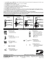
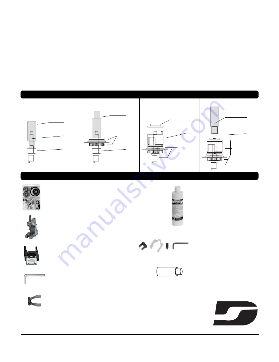
Drawing 1
Drawing 2
02695
Bearing
Drawing 3
Drawing 4
57091
Bearing Press Tool
57091
Bearing Press Tool
57091
Bearing Press Tool
01206
Bearing
Cylinder w/Front
Bearing Plate,
Lock Ring,
Pinion Gear
and Shaft
56595
Cylinder
54629
Rear Bearing Plate
Lock Ring and
Pinion Gear
Lock Ring,
Pinion Gear
and Shaft
56052
Bearing
96283 Motor Repair Kit:
•
Contains special tools for
disassembly/assembly of machine.
56589
Shaft
56052
Bearing
96213 Bearing Removal Tool
•
This tool is used to pass through the I.D.
of the bearing plate and to push against
the I.D. of the bearing.
96343 Retaining Ring Pliers
•
Internal/external retaining ring pliers.
Tip diameter - 0.038" (0.96mm)
95134
– 9/64" Hex Wrench
95135
– 5/32" Hex Wrench

