background image

Models:

58500 -

Non- Vacuum

(74mm x 109mm Pad)

58501 -

Vacuum-Ready

(74mm x 109mm Pad)

58502 -

Central Vacuum-Ready

(74mm x 109mm Pad)

58503 -

Non- Vacuum

(80mm x 130mm Pad)

58504 -

Vacuum-Ready

(80mm x 130mm Pad)

58505 -

Central Vacuum-Ready

(80mm x 130mm Pad)

Parts Page Reorder No. PD04•24

Effective May, 2004

Dynabug

II

Tool Manual – Safety, Operation and Maintenance

WARNING

WARNING

Read and understand tool manual before

work starts to reduce risk of injury to

operator, visitors, and tool.

WARNING

Eye protection must be worn at all times,

eye protection to conform to ANSI Z87.1.

WARNING

Respiratory protection to be used when exposed to

contaminants that exceed the applicable threshold

limit values required by law.

WARNING

Practice safety requirements. Work alert,

have proper attire, and do not operate tools under

the influence of alcohol or drugs.

WARNING

Ear protection to be worn when exposure to sound,

exceeds the limits of applicable Federal, State or

local statues, ordinances and/or regulations.

WARNING

Electric shock hazard. Avoid bodily contact with

grounded objects, bodies of water.

Do not damage cord set.

Read and understand this tool manual before operating your air tool. Follow all safety rules for the protection of operating personnel
as well as adjacent areas. Always operate, inspect and maintain this tool in accordance with the American National Safety Institute
(ANSI) Safety Code for Portable Air Tools – B186.1. For additional safety information, refer to Safety Requirements for the Use, Care
and Protection of Abrasive Wheels – ANSI B7.1, Code of Federal Regulation – CFR 29 Part 1910, European Committee for Standards
(EN) Hand Held Non-Electric Power Tools – Safety Requirements and applicable State and Local Regulations.

SAVE THIS DOCUMENT, EDUCATE ALL PERSONNEL

SAFETY LEGEND

SAFETY INSTRUCTIONS

Carefully Read all instructions before operating or servicing any Dynabrade

®

Abrasive Power Tool.

Products offered by Dynabrade are not to be modified, converted or otherwise altered from the original design without expressed written consent from Dynabrade, Inc.

Tool Intent:

Dynabug

II

Sander is used for sanding and finishing a variety of materials including wood, metal, plastic, fiberglass, solid surfaces,

composites, rubber, glass and stone.

Do Not Use Tool For Anything Other Than Its Intended Applications.

This power tool is not intended for use in potentially explosive atmospheres and is not insulated against contact with electrical power.

Training: 

Proper care, maintenance, and storage of your tool will maximize its performance.

• Employer's Responsibility – Provide Dynabug

II

operators with safety instructions and training for safe use of tools and accessories.

Accessory Selection:

• Abrasive/accessory RPM (speed) rating MUST be approved for AT LEAST the tool RPM rating.
• Before mounting an accessory, visually inspect for defects. Do not use defective accessories.
• Follow tool specifications before choosing size and type of accessory.
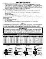
• Only use recommended fittings and air line sizes. Air supply hoses and air hose assemblies must have a minimum working pressure rating of 150 PSIG (10 bars, g) or 150 

percent of the maximum pressure produced in the system, whichever is higher. (See Tool Machine Specifications Table.)

(continued on next page)

10,000 RPM, 3/32" Orbit

Summary of Contents for Dynabug II

Page 1: ...ls ANSI B7 1 Code of Federal Regulation CFR 29 Part 1910 European Committee for Standards EN Hand Held Non Electric Power Tools Safety Requirements and applicable State and Local Regulations SAVE THIS DOCUMENT EDUCATE ALL PERSONNEL SAFETY LEGEND SAFETY INSTRUCTIONS Carefully Read all instructions before operating or servicing any Dynabrade Abrasive Power Tool Products offered by Dynabrade are not ...

Page 2: ...ing the accessory before testing or use and or after assembling tool the DynabugIImust be started at a reduced speed to check for good balance Gradually increase tool speed DO NOT USE if tool vibration is excessive Correct cause and retest to insure safe operation Make sure that work area is uncluttered and visitors are at a safe range from the tools and debris Use a vise or clamping device to hol...

Page 3: ...tolerances The failure of quality pneumatic motors can most often be traced to an unclean air supply or the lack of lubrication Air pressure easily forces dirt or water contained in the air supply into motor bearings causing early failure It often scores the cylinder walls and the rotor blades resulting in limited efficiency and power Our warranty obligation is contingent upon proper use of our to...

Page 4: ...e Muffler 31 57066 Muffler Body 32 56027 Muffler Insert 2 33 56028 Muffler Cap 34 01464 Seal 35 58365 Tip Valve 36 01468 Spring 37 01494 Inlet Bushing 38 57897 Vacuum Tube 39 57083 Vacuum Adapter 40 96197 Dowel Pin 41 95526 O Ring 42 57068 Vacuum Nozzle 43 57067 Vacuum Tube 44 57093 Vacuum Adapter Index Key No Part Description Adhesive A2 Loctite 271 A3 Loctite 243 A8 Loctite 567 Torque N m x 8 85...

Page 5: ... the 59083 Felt Washer into the 59057 Seal and place these onto the shaft balancer See Drawing 1 3 Use the small end of the 57091 Bearing Press Tool along with the arbor press to install the 58368 Bearing onto the shaft balancer See Drawing 2 Note Be certain that the felt washer does not get pinched between the bearing and the shaft balancer 4 Use the large end of the 57091 Bearing Press Tool to i...

Page 6: ...Adapter 2 Install the 57896 Felt Seal onto the 57897 Vacuum Tube Insert the muffler body and cone muffler through the 57093 Vacuum Adapter 3 Use the 96034 12mm Hex Key to secure all of these components to the housing 4 Install the 56027 Muffler Inserts 2 and push the muffler cap onto the muffler body 5 Attach the sander to the central vacuum system Self Generated Vac to Central Vac 1 Use a 1 8 dia...

Page 7: ... Cylinder 1 X 18 01024 O Ring 1 T L 19 59077 Rear Bearing Plate 1 X 20 98463 Retaining Ring 1 T L 21 57890 Isolator Post 4 1 X 22 See Note Housing 1 T L 23 57888 Throttle Lever 1 X 24 98927 Pin 1 T X 25 98459 O Ring 1 T X 26 58363 Valve Stem 1 T X 27 59075 Speed Regulator 1 X 28 01025 O Ring 2 T X 29 95697 Retaining Ring 1 T L 30 57065 Cone Muffler 1 T R1 31 57066 Muffler Body 1 X 32 56027 Muffler...

Page 8: ... International Fax 716 631 2524 DYNABRADE EUROPE S àr l Zone Artisanale L 5485 Wormeldange Haut Luxembourg Telephone 352 76 84 94 1 Fax 352 76 84 95 1 DYNABRADE INC 2004 PRINTED IN USA Visit Our Web Site www dynabrade com Email Customer Service Dynabrade com 1 American National Safety Institute ANSI 24 West 43rd Street Fourth Floor New York NY 10036 Tel 1 212 642 4900 Fax 1 212 398 0023 3 European...

Reviews: