3
Disassembly/Assembly Instructions - Dynafine
®
(Continued)
4. Loosen the 95884 Boot clamp and remove the boot assembly.
5. Use a 3 mm adjustable pin spanner wrench or the 50971 Lock Ring Tool to remove the 57962 exhaust Cover by turning it counterclockwise.
6. Pull the exhaust cover along with the motor assembly from the 01546 Housing.
7. Fasten the 96346 (2 in.) Bearing Separator around the end of the 01476 Cylinder that is closest to the 02673 Rear Bearing plate. Place the bearing separator on the table
of the 96232 #2 Arbor Press so that the 57961 Cam Assembly is pointing toward the floor. Use a 3/16" dia. flat end drive punch as a press tool and push the rear stem of
the 50777 Rotor out of the 02696 Bearing.
8. The 02696 Bearing can be removed from the rear bearing plate with a 96210 Bearing Removal Tool and the arbor press.
9. Secure the 50777 Rotor in a vise with an aluminum or bronze jaw and remove the 57961 Cam Assembly by turning it counterclockwise.
10. Remove the front bearing/plate from the 50777 Rotor with a 3/16" dia. flat end drive punch and the arbor press.
Motor Disassembly Complete.
Valve Disassembly:
1.
Place the 52296 Repair Collar around the valve housing and secure it in a vise so that the air inlet is pointing up.
2.
Use two wrenches to remove the air fitting or the 94407 Flow Control from the 94523 Inlet Adapter.
3.
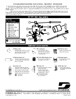
Loosen the 94523 Inlet Adapter from the valve housing and remove the 94520 Muffler Assembly. Note: Use the exploded view of the muffler assembly on the front of this
parts page to identify the specific components and their proper order of assembly.
4.
Remove the 12132 Pin and the throttle lever with a drive punch.
5.
Use retaining ring pliers to remove the 95558 Retaining Ring and the 01469 Speed Regulator Assembly along with the 01449 Valve Stem.
Valve Disassembly Complete.
Motor Assembly:
Important: Clean and inspect all parts for defects before assembling.
1. Use the 01476 Cylinder as an adjustment jig. Place the cylinder on the table of the arbor press.
2. Position the 50777 Rotor inside the cylinder so that the front face of the rotor is even with the top edge of the cylinder.
3. Install the 53161 Front Bearing Plate onto the rotor and cylinder so that the flat side of plate faces the vane slots of the motor.
4. Place the 56305 Bearing onto the front shaft of the rotor. Using a 96244 Bearing Press Tool, press against the inner race of the bearing pushing it down to the
bearing plate and cylinder.
5. Secure the 50777 Rotor in a soft jaw (aluminum or bronze) vise with bearing plate assembly pointing up.
6. Place the 57962 Exhaust Cover over the bearing/plate assembly.
7. Apply a small amount of #271 Loctite (or equivalent) to the threads of the 57961 Cam Assembly and install it onto the rotor , torque to 17 N•m/150 in.-lbs.
8. Remove this assembly from the vise and install 01480 Vanes that have been lubricated with Dynabrade Air Lube (10W/NR) or (equivalent oil).
9. Place 01476 Cylinder onto the assembly so that the air inlet of the cylinder will line up with the air inlet holes in the 02673 Rear Bearing Plate.
10. Use the 96216 Bearing Press Tool so that the press tool rest against the outer race of the 02696 Bearing and press the bearing all the way into the 02673 Rear Bearing Plate.
11. Position the motor assembly in the arbor press with the 57961 Cam Assembly resting on the table of the arbor press. Use the opposite end of the 96216 Bearing Press
Tool so that the press tool rest against the inner race of the 02696 Bearing. Carefully press the rear bearing/plate assembly onto the 50777 Rotor until the 02673 Rear
Bearing Plate comes in contact with the cylinder. Achieve a snug fit between the bearing plates and the cylinder while still being able to push the cylinder from side to side
with a slight force.
12. Apply a small amount of grease to the seal of the 02696 Bearing and position the 02679 Shield against the bearing.
13. Install the motor assembly into the 01546 Housing making sure that it slides all the way in.
14. Apply a small amount of Loctite #567 (or equivalent) to the threads of the 57595 Housing and thread the 57962 Exhaust Cover onto the housing.
15. Apply a small amount of Loctite #609 (or equivalent) to the outer race of the 11016 Bearing. Use the 96243 Bearing Press tool to push against the outer race of the
bearing and press the bearing into the boot assembly.
16. Apply a small amount of the 95542 Grease (or equivalent) to the shaft of the cam assembly and install the boot assembly along with the 95884 Boot Clamp.
17. Tighten 95884 Boot Clamp and torque to .68 N•m/6 in.-lbs.
18. Use the 95266 (3 mm) Hex Key to install the sanding attachment.
Motor Assembly Complete.
Valve Body Assembly:
1. Place the 52296 repair Collar around the valve housing and secure it in a vise so that the air inlet is pointing up.
2. Install the 01469 Speed Regulator Assembly (includes o-rings) along with the 01449 Valve Stem into the valve housing. Secure the speed regulator assembly in the valve
housing with the 95558 retaining Ring.
3. Install the 01464 Seal into the air inlet opening of the valve housing.
4. Line up the hole in the 01449 Valve Stem with the air inlet hole in the valve housing. Use needle nose pliers to insert the 01472 Tip Valve into the air inlet hole of the valve
housing so that the metal stem of the tip valve passes through the hole in the valve stem.
5. Install the 01468 Spring so that the small end of the spring fits onto the back end of the 01472 Tip Valve.
6. Install the 96065 O-Ring onto the 57970 Air Control Ring. When installing these into the valve housing make sure to line up the holes in the air control ring with the
exhaust area of the valve housing.
7. Assemble the 94520 Muffler. Note: Use the exploded view of the muffler assembly on the front of this parts page to identify the specific components and their proper
order of assembly.
8. Apply a small amount of the Loctite #567 (or equivalent) to the threads of the 94523 Inlet adapter and install the muffler assembly onto the valve housing.
(Torque to 23 N•m/200 in.- lbs.)
9. Install the throttle lever and secure it in place with the 12132 Pin.
Tool Assembly Complete. Please allow 30 minutes for adhesives to cure before operating tool.
Throttle Lever Positioning Procedure:
1. Place the 52296 repair Collar around the valve housing and secure it in a vise so that the 01546 Housing is pointing up.
2. Slip the 01558 Collar down onto the valve housing to expose the 01461 Lock Nut.
3. With a firm hold on the 01546 Housing, use a 34 mm or an adjustable wrench to turn the 01461 Lock Nut counterclockwise to loosen the 01546 Housing from the valve housing.
(continued on next page)


