background image

27

14.3  NRS 90222 remote module ......................................................................................................... 69
14.4  NRS 90224 pilot tone and ground fault surveillance........................................................................ 70

15.   Warranty ........................................................................................................................................... 72

1.

Utilization

The amplifiers DPA 4120 and DPA 4140 are specially designed for the power-consistent and reliable operation of PA-
systems. The DPA 4120 and DPA 4140 are intended to be used in company intercom, alarm and background music
transmission installations, offices and commercial areas, congregation and sport centers, schools, churches, hotels,
hospitals, shopping malls and super markets, cruise ships, and other similar applications.

2.

Installation

When installing the amplifiers, it is important to assure that for ventilation reasons the front-to-rear air circulation is
guaranteed (for details on 19"-case or 19“-rack shelf installation please refer to paragraph 9).

To maintain EMC it is necessary that all input, output, and control lines – except for the power cords – are shielded.
Within metal housings or closed rack shelf systems, unshielded output and control cabling is allowable. Shielding is
accomplished by connecting the individual cable screens to the enclosure or rack shelf ground potential.

The amplifier has to be protected from:

 - water drops or splashes
 - direct sunlight
 - high ambient temperatures and the direct radiation of heat sources
 - high humidity and moisture
 - heavy dust
 - massive vibrations

Moving the amplifier from a cold into a warm environment can result in the occurrence of condensation on inner parts.
Operating the appliance is only permissible after it has accommodated to the altered temperature (approximately after
one hour).

Should it happen that foreign solid parts or liquids inadvertently intrude the enclosure, unplug the device from the
power source and have it checked by a DYNACORD service center, before using it again.

Cleaning the appliance should not be performed using chemical solvents or sprays, as this might damage the finish
and moreover could cause hazard fire.

3.

Before the first operation

These power amplifiers are designed to be operated with different input modules. The general input module NRS
90225 is meant for all conventional applications. It allows to remotely start the amplifiers via control lines, monitor their
operation by use of the incorporated fault relay, and monitor the transmitted audio signals through the monitor output.
Using the remote control module NRS 90222, the amplifiers are connected to the PROMATRIX manager DPM 4000
via RS-485 remote interface providing complete remote operation and surveillance. The desired input module has to be
inserted into the module shaft on the rear of the power amplifier. It has to be tightened using the two locking screws
(B) (refer also to the paragraphs 8.1 and 8.2).

3.1

Mains operation

For normal AC mains operation, the included mains cord has to be connected to a 230V or 115V 50/60Hz wall outlet.
On the appliance itself, the cord has to be connected to the 3-pole mains socket (10).

 Caution

The appliance is factory preset to 

230V AC

. Switching to 115V AC is accomplished using the voltage

selector (12).

Summary of Contents for Power Amplifier DPA 4120

Page 1: ...er or REMOTE MODULE for controlling and monitoring the PROMATRIX system electronic level controls electronically balanced input and MONITOR output with optional transformer integrated stand by power supply mains POWER ON OFF switch ground lift switch remotely controllable mains and battery operation with initial current inrush limiter power on switching noise suppression status LED indicators for ...

Page 2: ...24 ...

Page 3: ...15V T 4AFOR230V GR OUN DED UNGR OUN DED C HASSIS SWITCH CIR CUIT TO AC MAINSINPUT VOLTAGE SELECT OR 115V 230V DC INPUT 24V 1 2 3 4 5 POWEROUTPUT DPA 4140 121629 NO U SER SER VICEABLE PARTS IN SID E REFER SERVIC ING TO QUALIFIED SERVICE PERSONNEL AD DRESS O UTPUT VO LTAGE A B VO R Ö FFNEN DES G ERÄTES NETZSTECKER ZIEHEN M ADEIN GERMANY CAUTION FORCON TINUED PRO TECTIONAGAIN STR ISKOFFIRE REPLACEWIT...

Page 4: ... the output voltage 31 8 Enhanced application field 32 8 1 General input module NRS 90225 32 8 2 Remote module NRS 90222 32 8 3 NRS 90208 input transformer for the floating balanced input 33 8 4 NRS 90227 output transformer for the floating balanced monitor output 33 8 5 NRS 90224 pilot tone and ground fault surveillance 35 8 5 1 Pilot tone surveillance 35 8 5 2 Ground fault surveillance 35 9 19 c...

Page 5: ...ndensation on inner parts Operating the appliance is only permissible after it has accommodated to the altered temperature approximately after one hour Should it happen that foreign solid parts or liquids inadvertently intrude the enclosure unplug the device from the power source and have it checked by a DYNACORD service center before using it again Cleaning the appliance should not be performed u...

Page 6: ... to battery is performed via integrated relays The battery has to be connected on the rear of the amplifiers 20 using insulated 6 3x0 8 mm AMP flat plug connectors The amplifiers are protected against polarity mismatch Each the positive and negative conductors are internally protected by fuses located on the printed board assembly 85270 DPA 4120 respectively 85268 DPA 4140 see also paragraph 11 fi...

Page 7: ...e plug in bridge B411 on the printed board assembly 84187 DPA 4120 respectively 84175 DPA 4140 see also paragraph 7 figure 3 connection of the power output 5 2 POWER OUTPUT for 100V 70V or 50V loudspeaker systems If the distance between the amplifier and the loudspeakers exceeds 50 m it is recommended to operate the speaker systems using 100V matching transformers to reduce line attenuation This a...

Page 8: ...5 allows the connection of an additional power amplifier for monitoring purposes The low impedance output is electronically balanced which offers the possibility to achieve cable lengths of up to 200 m Connection is performed via the REMOTE CONTROL pin connector strip see also figure 4 For the remote control module NRS 90222 the MONITOR output is located on the REMOTE CONTROL connector 22 The PROM...

Page 9: ... 2 allow to monitor the output level effectively avoiding overdrive conditions that lead to distortion and overload at the power outputs which could damage the connected loudspeaker systems If the red CLIP LED 2 shortly lights during program peaks maximum non distorted modulation is achieved Continuous lighting or blinking of the red CLIP LED 2 signals overdrive In this case the input level has to...

Page 10: ...fault messages via the READY relay contact thermal overload of the mains transformer thermal overload of the power amplification stage ground fault optional only with installed NRS 90224 pilot tone signal optional only with installed NRS 90224 MONITOR output electronically balanced input transformer for floating balanced input optional output transformer for floating balanced monitor output option...

Page 11: ...monitor the operation of the power amplifiers DPA 4120 and DPA 4140 from the PROMATRIX manager DPM 4000 for further details please refer to the PROMATRIX handbook Caution Before installing the input module NRS 90222 you have to unplug the mains connector as well as a presumably connected battery cord Before installing the input module it is necessary to remove the two locking screws B on the rear ...

Page 12: ...tion has to be performed as follows see figure 6 and or figure 7 to remove the input module you have to loosen the two locking screws B on the rear panel of the appliance Now the module can be easily torn out before installing the output transformer you have to remove the resistors R22 R23 R32 and R33 NRS 90225 respectively the resistors R23 R24 R71 and R72 NRS 90222 now you can mount the output t...

Page 13: ... pilot tone signal is introduced to the signal path following the input level control LEVEL After passing the amplifier stages the pilot tone signal is filtered out at the output and the result is evaluated If the measured signal declines the pilot tone s predetermined threshold at the output or is not present at all the READY indicator 7 dims and the READY fault message relay drops When using the...

Page 14: ...ed via the red GROUND FAULT indicator 6 In case of an inserted INPUT MODULE NRS 90225 it is also outputted as collective fault message with the floating contact of the READY fault message relay via the REMOTE CONTROL connector 16 When using the REMOTE MODULE NRS 90222 error occurrence is monitored and output by the PROMATRIX manager DPM 4000 for further details please refer to the PROMATRIX handbo...

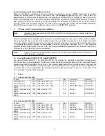
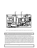
Page 15: ...37 figure 8 printed board assembly 84187 in the DPA 4120 showing the NRS 90224 pilot tone ground fault surveillance and the bridges B411 and S405 S406 for switching the output voltage inserted B 411 ...

Page 16: ...r amplifier is switched on the green READY indicator 7 has to light The testing and reset button TEST 3 serves as a function control for the pilot tone surveillance With the TEST button being engaged the 19 kHz generator is inactive The green READY indicator is off and the READY fault message relay drops Approximately 3 seconds after releasing the TEST button the indicator has to light again This ...

Page 17: ...helf or rack case have to be taken into careful consideration Note To ensure trouble free operation of the appliance the maximum permissible ambient temperature of 40 C is not to be exceeded 10 Ground lift switch CIRCUIT TO CHASSIS SWITCH The ground lift switch CIRCUIT TO CHASSIS SWITCH 19 provides the possibility to separate the signal ground from the enclosure ground potential This is mainly mea...

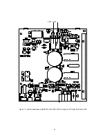
Page 18: ...40 F 503 F 502 figure 10 printed board assembly 85270 in the DPA 4120 showing the DC fuses F502 and F503 ...

Page 19: ...41 F 503 F 502 figure 11 printed board assembly 85268 in the DPA 4140 showing the DC fuses F502 and F503 ...

Page 20: ...he rear panel of the appliance Therefore detach the yellow green cable from the ground connector on the appliance s rear panel Pressing the lock strap of the AMP connector together it can be removed without applying any force Now you have to remove the three screws marked A refer to the diagram of the appliance s rear panel on page 2 which allows you to twist the power supply input PCB 86243 up Ma...

Page 21: ... 115 4 54 522 415 200 215 initial current inrush mains 20 A Pmains VA apparent power Umains Imains Pmains W true power Pout W output power Pv W leakage power battery operation 24 V DC 10 30 battery operation UB V IB A Pi W Pout W Pv W stand by 24 2 5m 60m 0 60m idling 24 0 43 10 0 10 normal operation 10 dB 24 3 74 90 20 90 standard conditions 24 9 10 218 131 87 initial current inrush battery 3 8 A...

Page 22: ...3 dB 115 6 20 713 562 200 362 standard conditions 115 8 86 1019 811 400 411 initial current inrush mains 21 A Pmains VA apparent power Umains Imains Pmains W true power Pout W output power Pv W leakage power battery operation 24 V DC 10 30 battery operation UB V IB A Pi W Pout W Pv W stand by 24 2 5m 60m 0 60m idling 24 0 62 15 0 15 normal operation 10 dB 24 7 1 170 40 130 standard conditions 24 1...

Page 23: ...pecifications DPA 4120 DPA 4140 13 3 NRS 90208 input transformer for floating balanced input frequency response 20 Hz 20 kHz input impedance 10 k ohms idling ratio 1 1 winding resistance primary 1420 ohms at 20 C winding resistance secondary 1420 ohms at 20 C 13 4 NRS 90227 output transformer for floating balanced monitor output frequency response 40 Hz 20 kHz nominal load impedance 600 ohms idlin...

Reviews: