background image

9

10

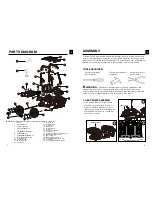
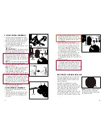
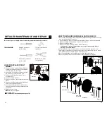
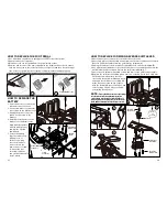
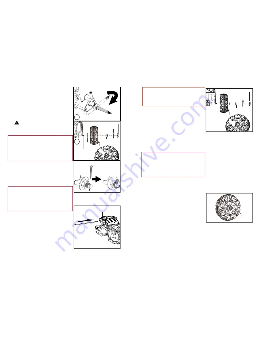
3. REAR WHEEL ASSEMBLY

•  First, remove all washers and nuts from 

the rear axle.

•  Insert the rear axle through the hole in the 

vehicle body as shown, making sure the 
axle exposure at the left and right ends 
are equal.

•  Find a rear wheel marked with an “R” 

and labeled with an “Rear”. Find the “R” 
marking at the rear end of the vehicle body 
to match this wheel and slide the wheel 
onto the axle.

•  Insert a Ø12 washer onto the axle.
•  While holding the rear axle with a 17mm 

socket wrench, fit the M10 locknut to the 
end of the rear axle with another 17mm 
socket wrench. DO NOT over tighten; the 
rear axle ends are supposed to be exposed; 
1-2 threads exposed is acceptable. 

•  For your safety, insert a split pin into the 

hole in the end of rear axle, and split it 
using standard needle nose pliers. (Refer 
to the drawings illustrated for front wheel at 
page 9).

•  Insert the axle cap.
•  Find the other rear wheel, marked with an 

“L” and labeled with and “Rear”. Find the 
“L” marking at the rear end of the vehicle 
body to match this wheel and slide the 
wheel onto the axle. Secure this wheel with 
the same steps as the other rear wheel 
above.

2. FRONT WHEEL ASSEMBLY

•  Turn the vehicle body upside down (this 

should be handled carefully by two adults)

•  Cut the tie on the front axle with scissors.
•  Adjust the front wheel axle until the axle 

clicks into position to ensure that it is 
secure for safety (see Figure A).

•  Remove washers and nuts from the front 

wheel axle.


 CAUTION:


 To avoid pinching your 

fingers, do not put your hand into the slot 
when adjusting the front wheel axle.

•  Fit a Ø19 washer onto the axle.
•  Find a front wheel marked with an “R” 

and labeled with an "Front". Find the “R” 
marking on the front of the vehicle body to 
match this wheel and slide the wheel onto 
the axle. 


NOTE

:  Refer to the below drawing showing 

"R" and "L" location on vehicle body.

•  Fit a Ø12 washer and M10 locknut onto the 

axle, then tighten it. 

•  Insert the axle cap until it clicks into place.
•  Find the other front wheel, marked with an 

“L” and labeled with and “Front”. Find the 
“L” marking on the front end of the vehicle 
body to match this wheel and slide the 
wheel onto the axle. Secure this wheel with 
the same steps as the other front wheel 
above.

•  Front wheels should spin freely; 

if not, loosen nut slightly.

Front Axle

Wheel Axle


Front Wheel

Ø12 

Washer

Ø19 

Washer

Spilt Pin

Spilt Pin

Spilt Pin

M10 

Lock Nut

Axle Cap

A

B

NOTE

:  Do not over-tighten. For your safety, 

make sure you insert a split pin into the 
hole in the end of front axle, and split it 
using standard needle nose pliers.

Fron

t

Rear Axle


Rear Wheel

Ø12 

Washer

Axle Cap

M10 

Lock Nut

Split Pin

Rea

r

Rear Axle

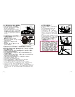
IMPORTANT! CHECK WHEEL GAP

After assembling any wheel onto the axles, 
check the gap between the screw thread 
and the outside of the wheel (refer to the 
adjacent diagram). 
If the gap is too big, add two or three 
washers on the axle to the inside of the 
wheel. After tightening the nut on the outside 
of the wheel, spin the wheel to check if the 
wheel spins smoothly. If the wheel gets 
caught or does not spin smoothly, the 
friction may cause damage to the motor. Try 
increasing the gap by removing one or two 
washers to ensure the wheel spins smoothly.

NOTE:


If the wheel nuts are loose, 

the wheels will not engage the 

forward gear. Tighten the nut with 

the socket wrench.  

Gap

"L"

"R"

Summary of Contents for 24V UTV

Page 1: ...keep the manual handy for future reference FOR AGES 3 MAXIMUM WEIGHT TOTAL 130 lb 59 kg 65 LB 29 5kg per seat 24V UTV OWNER S MANUAL NOTE Illustrations in this manual are for reference purposes only and may not reflect the exact appearance of the actual product Specifications are subject to change without notice DO NOT return this item to the store QUESTIONS OR COMMENTS 1 800 288 1560 ...

Page 2: ...er The ride on toy can and is intended to move and it is therefore possible to lose control fall off and or get into dangerous situations that no amount of care instruction or expertise can eliminate If such a thing does occur your child can become seriously injured or die even when using safety equipment and other safety precautions WARNING To reduce risk of injury adult supervision is required N...

Page 3: ... laws rules and common sense Children should be made aware of all possible riding hazards and correct riding behavior before they ride the electric ride on toy and should be supervised by an adult at all times Please explain the following to them as often as necessary SAFE RIDING PRACTICES AND WARNINGS Check and obey all local laws or regulations which may be in effect in the locations where the e...

Page 4: ...peration and That all safety labels are in place and understood by everyone including the riders Avoid sharp bumps drainage grates and sudden surface changes Do not ride in the rain or on wet surfaces PRE RIDE SAFETY CHECKLIST Check to make sure that all components are properly secured and are functioning according to the manufacturer s specifications Components must be maintained and repaired and...

Page 5: ...dy Use 4 pieces of M5x16 machine screws to tighten each corner first then tighten the rear middle with one piece of 4x16 flat heat screw securely Note Some parts shown are assembled on both sides of vehicle 1 Roof x1 2 Top LED Lamp x 1 3 U shape Support x 2 4 Roof Front Support x 2 5 Steering Wheel Assembly x 1 6 Front Basket x 1 7 Plastic Body Assembly x 1 8 Ø19 Front Axle Washer x 2 9 Front Whee...

Page 6: ... axle Fit a Ø19 washer onto the axle Find a front wheel marked with an R and labeled with an Front Find the R marking on the front of the vehicle body to match this wheel and slide the wheel onto the axle NOTE Refer to the below drawing showing R and L location on vehicle body Fit a Ø12 washer and M10 locknut onto the axle then tighten it Insert the axle cap until it clicks into place Find the oth...

Page 7: ...ding L and R markings on the roof panel and then fit each U shaped support to the corresponding spot on the roof panel as shown in the diagram to the right Secure the U shaped supports to the roof using 3 4x16 mm flat head screws on each support as shown in the diagram at right 7 ROOF FRONT SUPPORTS ASSEMBLY Find one Front Support marked with an R and attach it to the corresponding U shaped suppor...

Page 8: ...tteries of the same or equivalent type as recommended If rechargeable batteries are used they should only be charged by an adult Remove rechargeable batteries from the product before charging Battery chargers used with toys must be examined regularly for damage to the cord plug enclosure and other parts In the event that such damage is found the toy must not be used with the battery charger until ...

Page 9: ...nt angles you can change its angle by turning the lamp 12 FRONT BASKET ASSEMBLY Place the Basket into the four correspond ing holes in the Hood and push down until it clicks into place Use four 4x16 mm flathead screws to secure the basket to the Hood as shown in diagram 1 If you do not want the Basket on the Hood find the four small end caps supplied in the bag with the owners manual diagram 2 and...

Page 10: ...r in dry locations only IMPORTANT NOTE The battery must be upright while charging The charger is not a toy Do not short circuit the battery You do not need to remove the battery from your vehicle to recharge it Before charging the battery examine the battery case for cracks and other damage which may cause sulfuric acid electrolyte to leak during the charging process If damage is detected do not c...

Page 11: ... move the car forward at low speed shift the lever to the 1 position To move the car backward shift the lever to the R position NOTE Use low speed until you get familiar with your new vehicle WARNING The vehicle does not have brakes Do not park or ride on any slopes or steep inclines SOUND BUTTON To activate sound press the button on the steering wheel STOP To stop the vehicle you must take your f...

Page 12: ...ts inspect the vehicle before riding to ensure that it is in proper working order and safe to ride This toy has no brake to stop remove foot from the foot pedal Check all the screws cap nuts and protective coverings regularly and tighten as required Check plastic parts on a regular basis for cracks or broken pieces Your new battery must be charged for at least 18 hours before you use it in your ve...

Page 13: ...lt Pin M10 Lock Nut Axle Cap B Front HOW TO REPLACE REAR WHEEL AND GEAR BOX 1 Remove the axle cap by sliding a flat head screwdriver along the edge of the cap and carefully prying the cap open 2 Use needle nose pliers to remove the split pin in the hole of the rear axle end 3 Remove the M10 locknut with a 17 mm socket wrench 4 Remove the Ø12 washer 5 Remove the rear wheel and replace with a new wh...

Page 14: ... snaps into place HOW TO REPLACE FORWARD REVERSE SHIFT LEVER 1 Unscrew the two screws on the seat and remove the seat 2 Unscrew 4 pieces of 4x12 round head screws as shown to remove the Forward Reverse Shifter Assembly from the vehicle body diagram A 3 Unplug the switch sockets from the Forward Reverse switches diagram B 4 Use a flat head screwdriver to pry off the shift lever cover and then unscr...

Page 15: ...not dispose of the batteries in a fire as the battery may explode or leak The incineration disposal in landfill and or placing sealed lead acid batteries with household trash is prohibited by law in most areas Return exhausted batteries to a state or federal approved lead acid battery recycler or check with your local retailer of vehicle batteries If you live in Florida or Minnesota it is prohibit...

Page 16: ...al fuse may trip and shut down operation if the vehicle is overloaded or the driving conditions too severe Once a fuse has tripped remove your foot from the pedal and wait approximately 2 minutes before operating the vehicle again To avoid repeated automatic shutdowns do not overload the vehicle by exceeding the 130 lbs maximum weight capacity or by towing anything behind the vehicle Do not drive ...

Page 17: ...L PURCHASE PRICE AND IN NO EVENT SHALL DYNACRAFT BE LIABLE FOR INCIDENTAL OR CONSEQUENTIAL DAMAGES This Limited Warranty will be void if the product is ever used in a manner other than for recreation or transportation modified in anyway used as a rental Dynacraft does not offer an extended warranty if you have purchased an extended warranty it must be honored by the store from which you purchased ...

Page 18: ... when you call Model Number sample 8802 33 Production Date sample 03 03 2015 Serial Number sample DA0233HD00001 Having this information will be required and helps us handle your call more effectively Dynacraft BSC Inc 89 S Kelly Rd American Canyon CA 94503 Call Toll Free 1 800 288 1560 Monday Friday 7AM to 4PM PST www dynacraftwheels com 2018 All rights reserved 2018 Printed in China BM181 STOP ...

Reviews: