you will be using the Great Planes Isolation
Mount™ you will need to reposition the
Mounting Grommets as shown on the plan.
Note: Depending on the type of engine you are
installing, you may need to add spacers
between the engine mount and firewall. Layers
of aircraft grade 1/4" plywood (not included)
work well for this. The firewall location is
designed so that a typical gasoline engine can
be mounted on a Great Planes Isolation Mount
(GPMA2000, not included).
Gasoline Engine Note: Gasoline engines
mounted on an isolation mount, such as the
Great Planes Large Engine Isolation Mount™,
may need to be mounted on the centerline of
the model. This is needed to obtain clearance
between the mounting bolts of the isolation
mount and the engine on the relatively narrow
firewall. Shim the engine as needed to obtain 0°
of right thrust (about 1/8").
Most engines will fit inside the cowl if the engine
is mounted inverted. Be sure to allow for adequate
cooling.
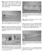
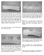
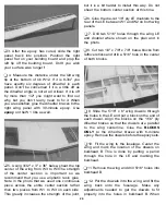
Q 27. Drill the 1/4" x 4-1/8" x 4-1/4" ply firewall
as needed for your engine mount and install
any required blind nuts. Glue the firewall to the
fuselage with 30-minute epoxy. For added security
you can pin the firewall to the fuselage if
desired. Drill small holes through the sides of
the fuselage into the firewall and epoxy in small
dowels or toothpicks.
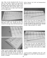
Ul 28. Once the epoxy has cured, install any
spacers needed for your engine mount. Be sure
to install any blind nuts required to bolt your
engine mount to the spacers.
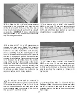
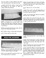
Q 29. Glue the die-cut 1/8" ply and balsa side
bulkhead formers A, B, C, D, E, F, G and H into
position on both sides of the fuselage. The flat
end of A and B goes towards the bottom of the
fuselage. The flat end of the rest of the formers
goes towards the top of the fuselage (E and F
can be glued on either way). The angled end of
C goes towards the bottom. Glue side former
DD to the rear of D. Note that DD is slightly
wider than D and should protrude from D by
about 1/32".
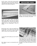
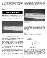
Ql 30. Cut two 3/16" x 3/16" x 24" balsa stringers
to length and glue them into place on side
formers DD, E, F, G and H.
Now is a good time to install the servos and
route the servo pushrods before any more
formers and sheeting are glued into place.
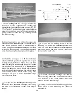
There are eight die-cut 1/8" ply pushrod guides
provided for this purpose. You may also need
some leftover 1/4" x 3/4" balsa sticks as well.The
plan shows the servos mounted just forward of
theTE of the wing.This is a good location if you
will be using a lighter engine such as a 1.20
4-stroke engine. Our prototype model, with an
O.S. FS-120 Surpass 4-stroke engine, balanced
without any lead required with the servos
positioned as shown on the plan. If you will be
using a heavier gasoline engine you may want
to mount the servos in the tail of the model.This
can be done easily by notching the longerons
for the servos, allowing them to protrude from
the fuselage side. If you do this, use some
leftover 1/4" x 3/8" basswood to reinforce the
longerons.
16


