All rights reserved. Reproduction or issue to third parties in any form whatsoever is not permitted without written authority from the proprietors.
7
3) Operation and Installation
3.1) General
The general sensor connector configuration is given below;
Cable Code/Pin Configuration:
• Red : V + Power supply v5 to +20 VDC
• Black : Ground Power GND
• X : Yellow : ) Positive, analog output voltage signal for differential mode.
Blue : Signal(-) Negative, analog output voltage signal for differential mode.
WARNING
Never connect the power supply and/or the power ground to yellow and/or blue
cables.
Never connect the power supply to the power ground. Always use a clean power
source and check the voltage range.
4) Sensor Static Calibration Verification
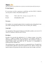
Using gravity, voltage values are measured in the + and – gravity directions, providing a value
of ±1 g. The measurement should be made as follows;
When the sensitivity value of 1000LN series sensors is used
with the data acquisition system, the sensor shows +1 g
with the effect of gravity
in the direction of the arrow sign.
When the sensor is in the opposite direction of the arrow,
it shows -1 g with the effect of gravity.
Using gravity, the voltage values that provide 1 g in the + and - directions are measured and
compared with the catalog value. The calibration value should be close to the catalog value with
10% tolerance. Sensor catalog sensitivity values are given in Table 1.


