background image


All rights reserved. Reproduction or issue to third parties in any form whatsoever is not permitted without written authority from the proprietors.


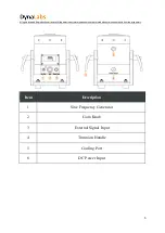
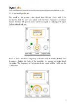
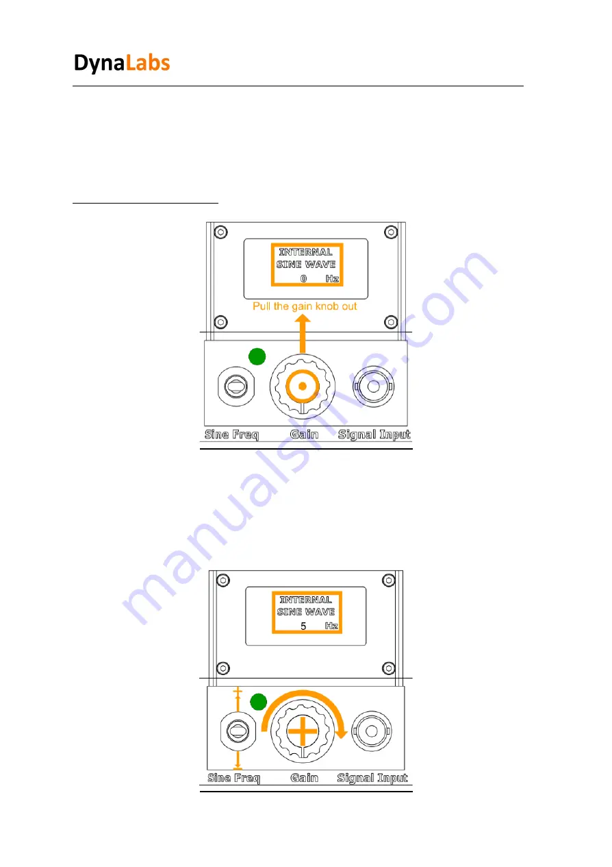
3.1.2 ) Internal Signal Mode:


The  amplifier  can  generate  sine  signal  from  1Hz  to  15kHz  with  1  Hz 
increments  that  the  user  can  adjust  with  the  Sine  Frequency  Generator 
Switch.  Connect  DC  power source  and drive  signal  to shaker power input. 
Pull the Gain Knob out.


Raise  or  lower  the  Sine  Frequency  Generator  Switch  to  the  desired  Sine 

frequency.  Adjust  the  Gain  of  the  amplifier  by  turning  the  Gain  Knob 
clockwise.  The frequency  of the generated  sine  signal  will  be visible  on the 
LCD Screen. 


Summary of Contents for DYN-PM-20

Page 1: ...Model DYN PM 20 20 N PM Shaker Product Manual ...

Page 2: ...ight All copyrights of this manual belonging to Dynalabs products are reserved It cannot bereproduced withoutwritten consent Disclaimer Dynalabs Ltd provides this publication as is without warranty of any kind express or implied including but not limited to the implied warranties of merchantability or fitness for a particular purpose This document is subject to change without notice and should not...

Page 3: ...king and Inspection 4 2 2 System Components 4 2 3 Theory of Operation 4 2 4 Specifications 6 2 5 Outline Drawing 7 3 Operation and Installation 8 3 1 General 8 3 1 1 External Signal Mode 8 3 1 2 Internal Signal Mode 9 3 2 Power Requirements 10 3 3 Cooling 10 3 4 Frequency Response 11 4 Mounting Interface 11 5 Maintenance and Troubleshooting 12 6 Safety 12 6 1 Grounding 12 7 Declaration of Conformi...

Page 4: ... that occur indirectly during the transport and contact the customer representative Check all components of the shaker If there is a defect please contact us 2 2 System Components The DYN PM 20 has the following components Electrodynamic Shaker Power Adapter Signal Cable M3X10 Stainless Bolt R 1 8 Pneumatic Union ProductManual 2 3 Theory of Operation DYN PM 20 is an electro magnetic actuator Elect...

Page 5: ... orissuetothirdparties in anyformwhatsoever is not permittedwithoutwrittenauthorityfromtheproprietors 5 Item Description 1 Sine Frequency Generator 2 Gain Knob 3 External Signal Input 4 Trunnion Handle 5 Cooling Port 6 DC Power Input ...

Page 6: ... Force Shock 40 N Frequency 0 12 kHz Payload 0 8 kg Displacement Peak to Peak 5 mm Suspension Spring Maximum Acceleration 40 g Shaker Weight 4 1 kg Cooling System NaturalConvection For continuousoperationat 20N forced cooling is suggested Operating Temperature Range 5 35 C Maximum Input Current 4A RMS AMPLIFIER INTERNAL ExternalSignalVoltageLevel 1 VAC PEAK Power SupplyVoltage 19V DC Power SupplyC...

Page 7: ...s reserved Reproduction orissuetothirdparties in anyformwhatsoever is not permittedwithoutwrittenauthorityfromtheproprietors 7 2 5 Outline Drawing The dimensional properties of DYN PM 20 shakers are given below ...

Page 8: ...rietors 8 3 Operation and Installation 3 1 General The general shaker connector configuration is given below 3 1 1 ExternalSignalMode Connect DC power source and drive signal to shaker power input and signal input respectively Start the external signal source Adjust the Gain of the amplifier by turning the Gain Knob clockwise ...

Page 9: ...z to 15kHz with 1 Hz increments that the user can adjust with the Sine Frequency Generator Switch Connect DC power source and drive signal to shaker power input Pull the Gain Knob out Raise or lower the Sine Frequency Generator Switch to the desired Sine frequency Adjust the Gain of the amplifier by turning the Gain Knob clockwise The frequency of the generated sine signal will be visible on the L...

Page 10: ...ower Requirements DYN PM 20 has an integrated power amplifier which is powered by its power adaptor Please note the output voltage and current ratings of the adaptor in a replacement adaptor is to be used 3 3 Cooling DYN PM 20 does not require forced cooling Air convection cooling is sufficient for the force levels given in the specifications ...

Page 11: ...ermittedwithoutwrittenauthorityfromtheproprietors 11 3 4 Frequency Response The following figure shows the acceleration levels Input voltage versus frequency of the shaker 4 Mounting Interface The shaker has five M3 holes for DUT and fixture connection as shown in the following figure ...

Page 12: ... proper repair 6 Safety Please ensure that this manual section is reviewed and understood prior to installation operation or maintenance of the equipment The danger of electrical shock or fire always exists in electrical equipment The DYN PM 20 Shaker is designed for safe operation Safety features such as electrical insulation on outer surfaces are provided for the safe operation of the shaker sys...

Page 13: ...ted according to following EC directives 2014 35 EU Low VoltageDirective LVD 2006 42 EU Machinery SafetyDirective 2015 863 EU RoHS Directive Applied standards EN 61010 1 2010 EN ISO 12100 2010 MIL STD 810 H 2019 Test Methods 501 7 High Temperature 502 7 Low Temperature 514 8 Vibration 516 8 Shock DYNALABSMÜHENDİSLİKSANAYİTİCARET LİMİTEDŞİRKETİdeclares that abovementioned productsmeet all the requi...

Reviews: