

3690 N.W. 53rd Street, For t Lauderdale, FL 33309 U.S.A.
(954) 739- 4300 • Fax: (954) 484-3376 • Web site: w w w.dynalco.com
© 2000 Dynalco Controls
1200F
DIP SWITCH SETTINGS
Switches 1 & 2 set the
full-scale frequency range
Switches 3 & 4 set the
overspeed relay logic
DIP
SW 1
DIP
SW 2
Full-Scale
Range
DIP
SW 3
DIP
SW 4
Re
Lo
OFF
OFF
=
0 – 11,200 Hz
ON
N/A
=
Ener
Ab
Setp
OFF
ON
=
0 – 5,000 Hz
OFF
N/A
=
De-En
Ab
Setp
ON
ON
=
0 – 1,000 Hz
N/A
ON
=
Latc
N/A
OFF
=
Doe
La
Installation and Calibration Instructions
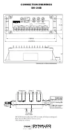
SW-200B Speed Switch
1. Installation: Mount the SW-200B to a secure bracket off the engine. If
on-engine mounting is necessary, shock mounts are recommended.
Wire according to connection diagram on reverse. Shielded cable is
recommended. Shield should be brought to ground directly. The
SW-200B will work with most magnetic pickups provided the signal
amplitude is greater than 50 mVrms and less than 70 Vrms. Mount
pickup according to manufacturer’s instructions.
2. Calibration: Determine the setpoint frequencies from an RPM value
using the following formula:
Frequency =
RPM x No. of Teeth (Holes)
60
A. Verify the current calibration: use a signal generator. Connect it to
the SW-200B magnetic pickup input.
B. Confirm the DIP switches are properly set for the frequency range and
overspeed relay logic desired. (See chart below.)
C. Set the signal generator output to at least 10% below the lowest setpoint.
Slowly increase the frequency. Using an ohmmeter across the relay
contacts, determine the frequency at which each relay changes state.
a. Change a setpoint: remove the appropriate access hole screw to reach
the setpoint's relay adjustment trim pot.
b. Set the signal generator to the frequency at which the relay should change
state. Connect it to the SW-200B magnetic pickup input.
c. Using a small, flat screwdriver, adjust the trim pot for the appropriate
relay until the relay changes state.
d. Decrease the frequency, then slowly increase it to verify that the relay
trips at the appropriate point.
Replace the access hole screw.
SW-200B is a trademark of Dynalco Controls
DYNALCO CONTROLS RESERVES THE RIGHT TO CHANGE THESE SPECIFICATIONS WITHOUT NOTICE.


