11
6) System
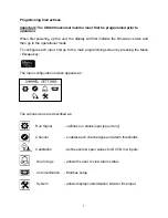
Using the arrows on the keypad, select the “System” icon.
There are (3) display layouts available. Selecting layout A, B or C will define the
preferred display type as follows:
Layout A:
Displays groups of (2) input channels plus differential.
Layout B:
Displays all inputs as bar graph plus each individual channel.
Layout C:
Displays each individual channel in large format.
Note that you are selecting the default layout type. You will be able to change the layout
during normal operation by pressing the left / right arrows.
Operation
Once programmed, the UM-600 will begin scanning all enabled channel inputs and will
initiate alarms based on over / under threshold values configured for each channel. It is
not necessary to define alarm threshold values for all channels as some may be for
monitoring only.
Alarm Outputs
The UM-600 will alarm when channel values or differential values are above or below
limits as specified. Alarms can be configured as either latching or non-latching. If an
alarm condition is met, the red LED on the front panel will blink and the digital output(s)
will trip. The alarm point name (ch1, ch2, df1, df2) that caused the alarm will be stored
in memory with date/time stamp info. Non-latching alarms will reset the alarm if its value
returns to normal. Latching alarms require manual resetting via the front keypad.
Selecting the alarm
icon will allow you to view any active alarms as well as the
history log for each channel. Once an active alarm is acknowledged, it will be placed
into the history log. The history log will continuously store the last 10 alarms for each
channel as well as the time & date of each alarm occurrence.
Summary of Contents for UM-600
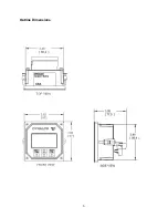
Page 6: ...5 Outline Dimensions ...
Page 13: ...12 ...


