background image

Page 1

2500/2280 WIRING 

SERIES 2500 & 2280 

ELECTROMAGNETIC LOCK

WIRING INSTRUCTIONS

1/07

Dyna

Lock

705 Emmett Street    Bristol, CT 06010

 1-877-DynaLock    www.dynalock.com

OVERVIEW

Familiarize yourself with the illustrations and instructions on this data sheet before attempting to wire this unit.
The circuit board illustrations show a lock with every possible option - your lock may not have certain options.

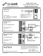
CIRCUIT BOARD DESCRIPTION & COMPONENT LOCATION

COIL CONNECTION AND VOLTAGE SELECTION

WHT
BLK
WHT
BLK

RED
WHT
GRN

COIL CONNECTOR
4-PIN PLUG

DYNASTAT CONNECTOR
3-PIN PLUG

POWER INPUT
12/24 VDC/VAC
NO POLARITY

VOLTAGE SELECTION
(SEE BELOW)

OPTIONAL
DOOR
STATUS
(DSM)

OPTIONAL
DYNASTAT
(DYN)

REMOVEABLE JUMPERS

VOLTAGE SELECTION

SET FOR 12 VOLTS

SET FOR 24 VOLTS

REMOVEABLE COIL

AND DYNASTAT

CONNECTORS

•  THE COIL AND DYNASTAT CONNECTORS ARE POLARIZED.  MAKE SURE  
    ALL PINS ARE CONNECTED.
•   ADJUST THE JUMPERS AS SHOWN BELOW TO MATCH THE INPUT
    VOLTAGE TO THE LOCK.  

ALL CONTACTS 
SHOWN IN UNSECURE 
/ DOOR OPEN STATE

WHT
BLU
BLK
RED

GRN
BRN
BLU

2280

2500

2280

2500

Summary of Contents for 2511 Series

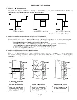
Page 1: ...re mounting hardware is supplied for a standard 1 3 4 thick door For thicker doors order the following special armature hardware kits Part 300687 for 2 thick doors Part 300688 for 2 1 4 thick doors HANDLING MAINTENANCE The Electromagnetic lock and armature are ruggedly constructed and designed to provide years of trouble free service Care must be taken during installation and use to keep the lock ...

Page 2: ... an angle bracket or filler plate will be required for installation The lock will require a 1 3 4 wide header stop for a suitable mounting surface Determine the hand of the door LHRB or RHRB and look at the template edge for proper positioning of the template A Fold the template on the dotted line to form a 90 degree angle B With the door in the closed and latched positon place the template agains...

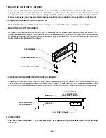
Page 3: ...ing holes and one 9 16 diameter wiring hole where shown Remove the Access and End Covers from the lock assembly see Exploded View page 4 Using the four 10 x 1 phillips flat head self tapping screws provided secure the lock assembly to the header Firmly tighten the screws with a 2 phillips head screw driver Locate the four anti tamper plugs and install over the mounting screw holes with a soft mall...

Page 4: ...t 1 1 8 Drill Bit 1 17 64 Drill Bit 1 1 4 Drill Bit 1 Hammer 1 Center Punch Pencil Tape 1 Mounting Instructions 1 Wiring Instructions 1 Electromagnetic Lock 1 Hardware Kit consisting of 4 10 x 1 Phillips Flat Head self tapping screws 4 Anti tamper Plugs 1 1 4 long Armature Spacer 1 1 8 thick Rubber Washer 1 1 16 thick Steel Washer 2 3 16 x 3 4 long Anti spin Pins 1 Template 1 Armature Bolt assembl...

Page 5: ...IPTION COMPONENT LOCATION COIL CONNECTION AND VOLTAGE SELECTION WHT BLK WHT BLK RED WHT GRN COIL CONNECTOR 4 PIN PLUG DYNASTAT CONNECTOR 3 PIN PLUG POWER INPUT 12 24 VDC VAC NO POLARITY VOLTAGE SELECTION SEE BELOW OPTIONAL DOOR STATUS DSM OPTIONAL DYNASTAT DYN REMOVEABLE JUMPERS VOLTAGE SELECTION SET FOR 12 VOLTS SET FOR 24 VOLTS REMOVEABLE COIL AND DYNASTAT CONNECTORS THE COIL AND DYNASTAT CONNEC...

Page 6: ...UTTON KEYSWITCH ETC WIRE MULTIPLE CONTROLS IN SERIES AS SHOWN CURRENT DRAW 2280 0 68A 12VDC 0 35A 24VDC 2500 0 50A 12VDC 0 25A 24VDC SHOWN PER COIL NC NO C DSM NC NO C DYN DYNALOCK CORP DOOR UNSECURE DOOR SECURE INPUT FROM INDICATOR POWER SOURCE DYNASTAT DYN OPTION LOCK STATUS BOND SENSOR DRY CONTACT RATING 0 25A 24VDC NOTE INDICATORS NOT INCLUDED DRY CONTACT RATING 0 25A 24VDC NOTE INDICATORS NOT...

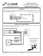
Page 7: ...istor from the black wire Connect the LED to the DYN as shown below LED OPTION LOCK DYN TIME DELAY TD MODULE WIRING Optional Model 7080 inline time delay module provides adjustable time delayed relocking This is a field installed device and wired per the following wiring diagram REMOVE FOR 12VDC OPERATION LED Red Door Locked Green Door Unlocked TD Module Trim Pot Rotate trim pot clockwise to incre...

Page 8: ...C SHOWN PER COIL SURGE SUPPRESSION Built in COIL RESISTANCE 2280 34 1 Ohms 10 Black White Red Blue 2500 53 8 Ohms 10 Black Black White White GENERAL SPECIFICATIONS PLEASE DELIVER THIS MANUAL TO THE END USER UPON COMPLETION OF THE INSTALLATION FOR PRODUCT SUPPORT AND PARTS ORDERING INFORMATION CONTACT DynaLock Corp 705 Emmett Street Bristol CT 06010 Bus 877 DYNALOCK Toll Free USA 860 582 4761 Fax 8...

Reviews: