Page 3
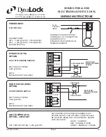
2500/2280 WIRING
SERIES 2500 & 2280
ELECTROMAGNETIC LOCK
WIRING INSTRUCTIONS
1/07
Dyna
Lock
705 Emmett Street Bristol, CT 06010
1-877-DynaLock www.dynalock.com
NC
C
NO
RESISTOR
LED
RED
BLACK
GREEN
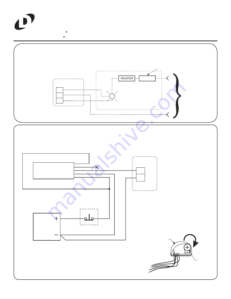
The Bi-Color LED is used in conjunction with the Dynastat (DYN) option to display lock status in two colors - red or green
and is pre-confi gured to operate on 24VDC. For 12VDC operation remove the outer resistor from the black wire. Connect
the LED to the DYN as shown below.
LED OPTION
LOCK - DYN
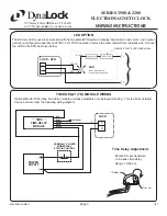
TIME DELAY (TD) MODULE WIRING
Optional Model 7080 inline time delay module provides adjustable time delayed relocking. This is a fi eld installed
device and wired per the following wiring diagram.
REMOVE FOR 12VDC OPERATION
LED
Red= Door Locked
Green= Door Unlocked
-
+
TD Module
Trim Pot
Rotate trim pot clockwise
to increase time delay.
Range = 0-60 sec.
Time Delay Adjustment
NORMALLY-CLOSED
MOMENTARY
STATION CONTROL
POWER
SUPPLY
RED
BLUE
GREEN
WHITE
BLACK
( )
( )
LOCK
(NOT USED)
TD OPTION
TIME DELAY
MODULE
1
2
+
-
7080
TIME DELAY
MODULE


