Page 4
3002xTJ32 MANUAL - FORM 3002TJ-003
MODEL 3002xTJ32
ELECTROMAGNETIC LOCK
INSTALLATION INSTRUCTIONS
02/07
705 Emmett Street Bristol, CT 06010
1-877-DynaLock www.dynalock.com
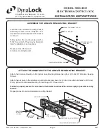
INSTALL THE ARMATURE MOUNTING BRACKETS
Use the fi gure below to identify and mark the locations of the armature mounting bracket screw holes on each door
leaf. Refer to door and frame prep drawing #301097 for further information.
1.
Mount the armature and mounting bracket assembly to the door using the appropriate hardware for you door type.
Firmly tighten the mounting screws with a 3/16” hex wrench.
Repeat process for second armature mounting bracket.
3.
4.
ARMATURE BRACKET
MOUNTING SCREW
LOWER ARMATURE
MOUNTING BRACKET
21/32”
SEX
NUT
DOOR
SPACER
ARMATURE BRACKET
MOUNTING SCREW
LOWER ARMATURE
MOUNTING BRACKET
5/16”-18
THREAD
Drill an 11/32” diameter hole
through door. From sex nut
side only enlarge the 11/32”
hole to 21/32” diameter.
Drill an 11/32” diameter hole
through door. From sex nut
side only drill 1/2” diameter
hole to 1” depth.
Drill an 11/64” diameter hole
and tap for 5/16”-18 thread.
GLASS & ALUMINUM
OR HOLLOW METAL DOOR
SOLID CORE DOOR
REINFORCED DOOR
From the illustrations below select the one that resembles your door type and follow the instructions for drilling the
two (2) armature mounting bracket screw holes.
2.
ARMATURE BRACKET
MOUNTING SCREW
1/2”
1”
LOWER ARMATURE
MOUNTING BRACKET
SEX
NUT
CL
CL
1-3/8”
FROM
FRAME
RABBET
1-5/8” FROM
CENTER OF
OPENING
CENTERLINE
1-5/8” FROM
CENTER OF
OPENING
7-3/4”
7-3/4”
1/4” MIN

