Page 5
3002xTJ32 MANUAL - FORM 3002TJ-003
MODEL 3002xTJ32
ELECTROMAGNETIC LOCK
INSTALLATION INSTRUCTIONS
02/07
705 Emmett Street Bristol, CT 06010
1-877-DynaLock www.dynalock.com
ARMATURE ADJUSTMENT
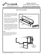
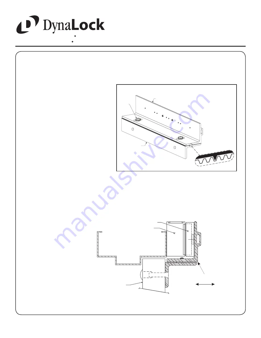
Using a 5/32” hex wrench, temporarily
loosen the armature bracket assembly
screws roughly 1-1/2 turns to allow the
upper armature bracket to move in and out
freely (Ref. Figure “A”).
Close and latch the door. The mating
surfaces of the lock and armature should
fully contact each other. If necessary, slide
the armature in or out to ensure full contact
is made with the lock while still allowing the
door to properly close and latch.
When the desired adjustment is achieved,
slowly open the door taking care to maintain
the position of the armature. Firmly tighten
the armature bracket assembly screws,
making sure that the locking ribs on the
upper and lower bracket halves properly
mesh (Ref. Figure “A”)
1.
2.
3.
Figure “A”
ASSEMBLY
SCREW
UPPER ARMATURE BRACKET
LOWER
ARMATURE
BRACKET
ARMATURE BRACKET
ADJUSTMENT RANGE
DOOR
ARMATURE
0”
1”
LOCK ASSEMBLY
NOTE:
Make sure the door hits the frame just
before the armature hits the maglock, to
prevent loosening over time (armature not
slamming against the lock).
1/8”

