Page 4
3101B MANUAL
02/08
MODEL 3101B
DELAY EGRESS SYSTEM
INSTALLATION INSTRUCTIONS
705 Emmett Street Bristol, CT 06010
1-877-DynaLock www.dynalock.com
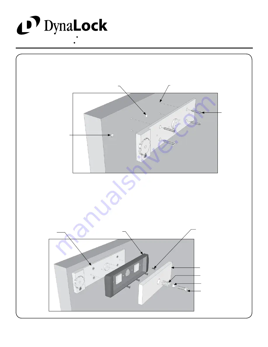
Using the four #10 x 1” flat head sheet metal screws attach the armature mounting plate to the door. Firmly tighten
the screws with a #2 phillips screw driver.
MOUNTING THE ARMATURE ASSEMBLY
Attach the Armature to the Mounting Plate Assembly using the hardware supplied. Apply the supplied thread locking
compound to the threads of the Armature Mounting Screw and firmly tighten with a 3/16” hex wrench. The head of
the armature mounting screw must not project beyond the face of the armature.
Failure to properly secure the
Armature to the door could result in serious injury or possible security breach.
Check the installation by pushing in on a corner of the Armature - it should move. Although the mounting screw is
tight the Armature should have approximately 1/4” of free play, under slight spring tension.
(4) 1/8” DIA. MOUNTING
SCREW HOLE - 1” DEEP
(1) 3/8” DIA. ARMATURE SCREW
CLEARANCE HOLE, 3/8” DEEP
(4) #10 X 1”
MOUNTING
SCREW
(1) 5/16” DIA. ADJUSTMENT
WHEEL SCREW CLEARANCE
HOLE - 1/4” DEEP
0.360”L ARMATURE SPACER
5/16-18x1” TURNED
ARMATURE MOUNTING
SCREW
ARMATURE
HOUSING
ARMATURE
8-32x3/8”
ARMATURE
HOUSING
SCREW
SPRING
ARMATURE MOUNTING
PLATE ASSEMBLY


