Leaders in Pipelin
e Survey Systems
C
C
C
-
-
-
S
S
S
C
C
C
A
A
A
N
N
N
2
2
2
0
0
0
1
1
1
0
0
0
SYSTEM MANUAL Version 6.03i
48
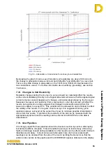
Fig. 7.1 – Maximum attenuations with soil resistivities
It is possible to reach or even exceed these maximum attenuation levels if the pipeline
being surveyed is in contact with a foreign object, which itself is shorted to ground, as this
can provide a lower resistance path than the surrounding soil.
7.3. Conductance
Within C-SCAN and DCAPP, figures are given for conductance as well as attenuation.
Conductance measures the coating’s ability to conduct an electric current. For a coating,
where its insulation property is paramount, this value is zero for a perfect (unattainable)
coating and infinite for bare pipe. The unit for conductance is Siemens (S) and it is the
reciprocal of resistance. The definition used in surveys has been defined by NACE in
TM0102-2002 (page 6) and is defined for pipeline coatings of various qualities as follows:
Less than
100
μ
S/m
2
Excellent
coating
100uS to
500
μ
S/m
2
Good to fair coating
500uS to
2000
μ
S/ m
2
Fair to bad coating
Above
2000
μ
S/ m
2
Bad to no coating
The unit
μ
S/m
2
is one-millionth (micro) of a Siemen per square metre. It should be noted
that the NACE values are calculated from a DC perspective and scaled for a soil resistivity
of 1,000
Ω
.cm. Conductance is always measured in
μ
S/m
2
regardless of input units
(metres or feet).
The conductance as defined gives a value per square metre such that a pipeline of 10m
length and 1m diameter will have the same area as a pipeline of 33m length and 30cm
diameter. Therefore to calculate the conductance the diameter must be known. If the
diameter is unknown the conductance will not be indicated, however, pipeline diameter
can be entered in DCAPP, post-survey, to calculate conductance if these details were not
know when the survey was carried out.


