Leaders in Pipelin
e Survey Systems
C
C
C
-
-
-
S
S
S
C
C
C
A
A
A
N
N
N
2
2
2
0
0
0
1
1
1
0
0
0
SYSTEM MANUAL Version 6.03i
55
8.5. Cross Bonds
Pipelines which run near to each other are frequently bonded to reduce the possibility of
corrosion being induced on one of them by a high CP potential on the other. These bonds
can usually be disconnected at CP test posts. It is usually advisable to disconnect all
cross-bonds for at least the next 3 to 6 miles when carrying out a survey. If this cannot be
done, the bonds will show up as ‘faults’ and some of the signal will be transferred to the
other line where it may be picked up during the survey. It is usually possible to distinguish
the ‘survey’ pipeline from the one carrying a signal returned via a cross-bond by the
considerable difference in signal strength.
8.6. Insulating Joints/Flanges
Where pipelines enter hazardous areas, or at the interface between a section protected by
sacrificial anodes and a section protected by an applied CP potential (e.g. at the shore
line), it is sometimes the practice to insert an insulating joint/ flange which electrically
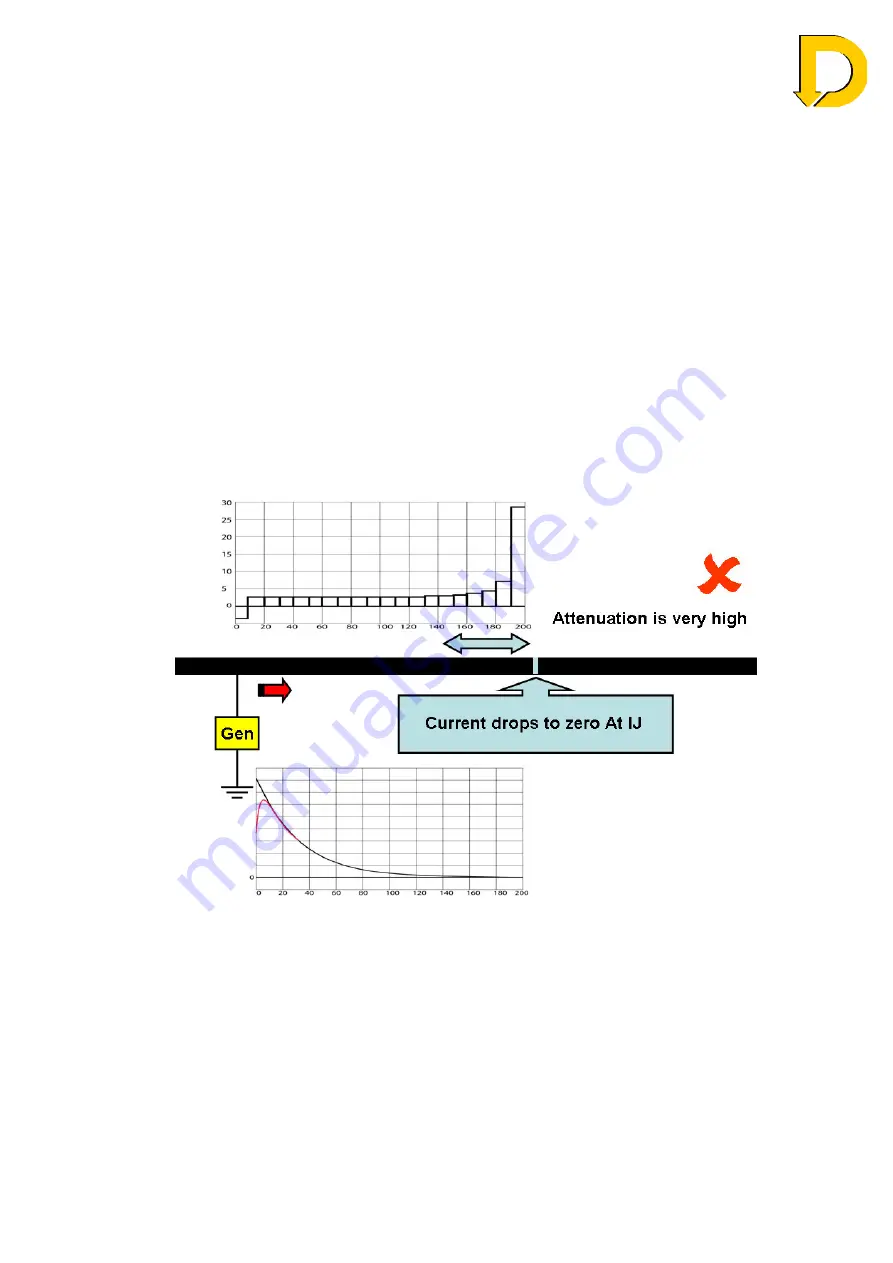
isolates one section of pipeline from the other. If the C-SCAN operator is surveying the
CP protected section and approaches such a flange, the signal level will drop rapidly and
there may be a very high apparent attenuation and depth over the last several hundred
feet before the flange as the entire signal must leave the pipeline before the Insulating
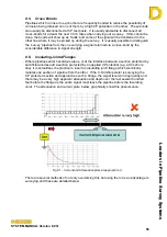
Joint. The attenuation and current plots, below, graphically show this phenomenon.
Fig 8.1 – Current and Attenuation plots at approach to IJ
There are several methods of not only overcoming this but using the IJ as an advantage to
surveying and these are detailed below.


