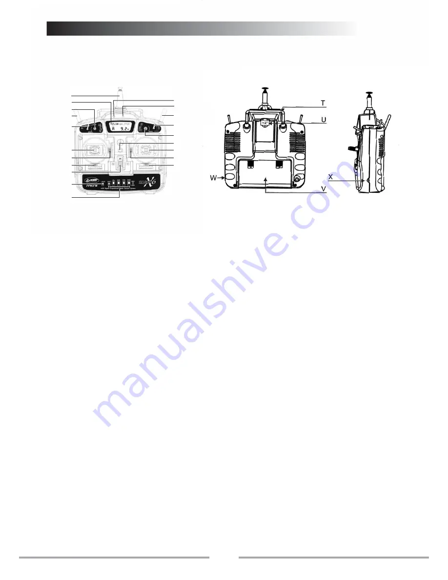
Transmitter particular introduce
7
A
B
C
E
G
K
O
M
Q
R
S
I
H
F
D
Y
J
N
L
P
A: Antenna
B: LCD(Liquid Crystal Display)
1)To indicate the battery voltage of transmitter.
2)To show the situation of channels whether it is reversed.
3)To show the flying time.
4)To indicate flying mode.
5)To indicate the status of lock and unlock.
C: Tiny Mix 1
D:Tiny Mix 2
E:Switch 1
this switch is for ch5 that can be used for aerial camera,
collapsible landing gear and shift between gyro mode and
gain, etc.
F:Switch 2
G:Flying mode switch
when the lock switch is on adjust, it is can be adjusted to
A/V/H/C Flying mode.
H:LED indicator for power
I:Red LED indicator for low voltage: when battery is under
8.5v, the LED will have a flash alarm; the LCD will cut off
when voltage is under 7.6v.
Note: when red LED flashes or nothing shows on LCD,
please change the battery in order to avoid flying out of
control.
J:Joystick
1)if the transmitter is model 1, ch1 is for aileron and ch3 for
throttle.
2)if the transmitter is model 2, ch1 is for aileron and ch2 for
rudder.
K:Joystick
1)if the transmitter is model 1, ch2 is for elevator and ch4
for rudder.
2)if the transmitter is model 2, ch3 is for throttle and ch4
for rudder.
L:Tiny mix for channels
1)
2)
if the transmitter is model 1, it is for ch3.
if the transmitter is model 2, it is for ch1.
M:Tiny mix for channels
1)if the transmitter is model 1, it is for ch1.
2)if the transmitter is model 2, it is for ch3.
N:Tiny mix for aileron
O:Tiny mix for rudder
P:Flying ring
Q:Switch for power
R:Lock switch
when the switch is on lock status, all are locked, including
switch for flying mode, tiny mix 1, and tiny mix 2 when
the switch is on adjust status, all can be changed,
including flying mode, tiny mix 1 and tiny mix 2.
S:ch1,ch2,ch3,ch4,ch6 reversed switched for changing
the turning of servo, up for reversed and down for
normal. REV: reversed NOR: normal
T:steel handle
U:tx crystal
V:battery bay for transmitter
W:plug for simulator
X:rechargeable plug(note:only 9.6v Ni-mh battery pack
can be recharged)
Y:Switch 3
the switch is to change the turning the turning range
of servos(100%/70%)for ch1,ch2,ch4.when it is 0,it
means the turning range of servos is 100%. When it is
1, it means the turning range of servos is 70%.


