Embedded Solutions
Page 28 of 37
Loop-back
The Engineering kit has reference software, which includes an external loop-back test.
The SDLC version of the PMC-BiSerial-III utilizes a 68 pin SCSI II front panel
connector. The test requires an external cable with the following pins connected.
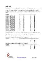
Using our HDEterm68 test fixture make the following connections (TP2 unless noted).
Note
: TP1, 2 are both ordered as follows: 1, 35
, 2, 36, 3, 37…32, 66, 33, 67, 34, 68.
SIGNAL
+
-
+
-
Chan 0 Data TX to RX
1
35
2
36
Chan 0 Clock TX to RX
3
37
4
38
Chan 1 Data TX to RX
5
39
6
40
Chan 1 Clock TX to RX
7
41
8
42
Chan 2 Data TX to RX
9
43
10
44
Chan 2 Clock TX to RX
11
45
12
46
Chan 3 Data TX to RX
13
47
14
48
Chan 3 Clock TX to RX
15
49
16
50
Chan 4 Data TX to RX
17
51
18
52
Chan 4 Clock TX to RX
19
53
20
54
Chan 5 Data TX to RX
21
55
22
56
Chan 5 Clock TX to RX
23
57
24
58
Chan 6 Data TX to RX
25
59
26
60
Chan 6 Clock TX to RX
27
61
28
62
Chan 7 Data TX to RX
29
63
30
64
Chan 7 Clock TX to RX
31
65
32
66
Additional I/O lines used for external clock tests-selectively connect to TX Clock lines
Eight six-pin headers are installed in TP1 occupying the following positions:
Pins 2-38, 6-42, 10-46, 14-50, 18-54, 22-58, 26-62 and 30-66.
External TX Clock Distribution Network to Channels 0-3
SIGNAL
+
-
+ (TP1) - (TP1)
TX Clock A
33
67
2
38
6
42
10
46
14
50
External TX Clock Distribution Network to Channels 4-7
SIGNAL
+
-
+ (TP1) - (TP1)
TX Clock B
34
68
18
54
22
58
26
62
30
66


