Embedded Solutions
Page 29 of 37
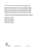
Four short wires per header are added to the bottom of the HDEterm68.
Channel 0: TP1 2 to 36, TP1 38 to 4, TP1 3 to TP2 3 and TP1 37 to TP2 37
Channel 1: TP1 6 to 40, TP1 42 to 8, TP1 7 to TP2 7 and TP1 41 to TP2 41
Channel 2: TP1 10 to 44, TP1 46 to 12, TP1 11 to TP2 11 and TP1 45 to TP2 45
Channel 3: TP1 14 to 48, TP1 50 to 16, TP1 15 to TP2 15 and TP1 49 to TP2 49
Channel 4: TP1 18 to 52, TP1 54 to 20, TP1 19 to TP2 19 and TP1 53 to TP2 53
Channel 5: TP1 22 to 56, TP1 58 to 24, TP1 23 to TP2 23 and TP1 57 to TP2 57
Channel 6: TP1 26 to 60, TP1 62 to 28, TP1 27 to TP2 27 and TP1 61 to TP2 61
Channel 7: TP1 30 to 64, TP1 66 to 32, TP1 31 to TP2 31 and TP1 65 to TP2 65
Installing two shunts per channel on the headers in TP1 will connect the external clock
to the respective channels, removing them allows internal clock tests to be performed.
Channel 0: 36-3 and 37-4
Channel 1: 40-7 and 41-8
Channel 2: 44-11 and 45-12
Channel 3: 48-15 and 49-16
Channel 4: 52-19 and 53-20
Channel 5: 56-23 and 57-24
Channel 6: 60-27 and 61-28
Channel 7: 64-31 and 65-32


