- 12 -
parts.
a
、
Disassemble four lock-nuts between foot
plate and pipe-protective, and then remove
foot plate.
b
、
Disassemble
six
screws
(M8×25)
between foot plate and pipe-protective.
c
、
Disassemble six screws (M12×35) among
foot plate, cover and spring cylinder, then
remove foot place.
NOTICE
!
Do not to remove two screws
(M12×25) between cover and spring cylinder
when you operate step “c”. Be careful to
spring and cover bounced.
d
、
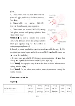
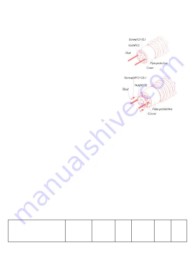
Install two stud (applicable types) in two disassembled screw (12×35)
positions , then attach two stud with two nut(M12) (applicable types) on
the cover. See right fig..
e
、
Remove two screw(M12×25) between cover and spring cylinder, then
slowly and equably remove two nut(M12). See right fig..
CAUTION
!
Keep people away from in the front two stud when remove
spring, serious injury.
CAUTION
!
Do not allow two stud to turn when remove spring. Be
careful bounce.
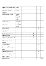
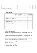
Maintenance schedule
Engine
:
Maintenance Items
Every
8 hours
(Daily)
Every
50 hours
(Weekly)
Every
100
hours
Every
200 hours
(Monthly)
Every
300
hours
Every
500
hours
Summary of Contents for TRE-75 TAMPING RAMMER
Page 1: ...TRE 75 TAMPING RAMMER Operation manual Dynamic world Dynamic life...
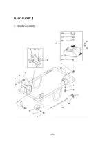
Page 21: ...20 DIAGRAME 1 Handle Assembly...
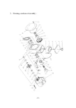
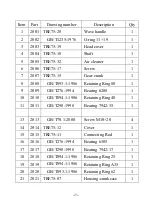
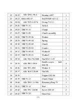
Page 23: ...22 2 Housing crankcase Assembly...
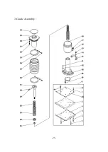
Page 26: ...25 3 Guide Assembly...
Page 29: ...28...
Page 30: ...29...
Page 31: ...30...


