background image


be present inside certain products even when the power switch (if installed) is in the OFF position or 
a fuse is blown. For DC-powered products, although the voltages levels are usually not hazardous, 
energy hazards may still exist. 
Before working on equipment connected to power lines or telecommunication lines, remove jewelry 
or any other metallic object that may come into contact with energized parts. 
Unless otherwise specified, all products are intended to be grounded during normal use. Grounding 
is provided by connecting the mains plug to a wall socket with a protective earth terminal. If an earth 
lug is provided on the product, it should be connected to the protective earth at all times, by a wire 
with a diameter of 18 AWG or wider. Rack-mounted equipment should be mounted only in earthed 
racks and cabinets. 
Always make the ground connection first and disconnect it last. Do not connect telecommunication 
cables to ungrounded equipment. Make sure that all other cables are disconnected before 
disconnecting the ground. 

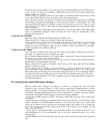
Connection of AC Mains 

Make sure that the electrical installation complies with local codes. 
Always connect the AC plug to a wall socket with a protective ground. 
Always connect the power cord first to the equipment and then to the wall socket. If a power switch 
is provided in the equipment, set it to the OFF position. If the power cord cannot be readily 
disconnected in case of emergency, make sure that a readily accessible circuit breaker or emergency 
switch is installed in the building installation. 

Connection of DC Mains 

Unless otherwise specified in the manual, the DC input to the equipment is floating in reference to 
the ground. Any single pole can be externally grounded. 
Due to the high current capability of DC mains systems, care should be taken when connecting the 
DC supply to avoid short-circuits and fire hazards. 
DC units should be installed in a restricted access area, i.e. an area where access is authorized only to 
qualified service and maintenance personnel. 
Make sure that the DC supply is electrically isolated from any AC source and that the installation 
complies with the local codes. 
Before connecting the DC supply wires, ensure that power is removed from the DC circuit. Locate 
the circuit breaker of the panel board that services the equipment and switch it to the OFF position. 
When connecting the DC supply wires, first connect the ground wire to the corresponding terminal, 
then the positive pole and last the negative pole. Switch the circuit breaker back to the ON position. 
A readily accessible disconnect device that is suitably rated and approved should be incorporated in 
the building installation. 

Preventing Electrostatic Discharge Damage 

Modules which can be plugged into chassis are sensitive to damage from static electricity. 
Conversely, static voltages as high as 35,000V can be generated just by handling plastic or foam 
packing material, or by sliding assemblies across plastic and carpets. Not exercising the proper 
electrostatic discharge (ESD) precautions can result in intermittent or complete component failures. 
To minimize the potential for ESD damage, observe the following guidelines: 
• Always use an ESD-preventive antistatic wrist strap or ankle strap and ensure that it makes good 
skin contact. 
• When removing or installing a component, make sure the equipment end of your antistatic strap 
leash is connected to the ESD connection sockets on the front of the chassis or to a bare metal 
surface on the chassis. Avoid contact between the component and your clothing. The wrist strap only 
protects the component from ESD voltages on the body; ESD voltages on your clothing can still 
cause component damage. 
• Always place a card component-side-up on an antistatic surface, in an antistatic card rack, or in a 
static shielding bag. If you are returning the item to the factory, immediately place it in a static 
shielding bag. 
• Handle Modules by the metal card carrier edges only; Avoid touching the board or any connector 
pins. 

Summary of Contents for FiberMix 2802-60FE-BL

Page 1: ...www godynamix com FiberMix 2802 60FE BL User Manual...

Page 2: ...language without the prior written consent of Dynamix Pro Ltd The information contained in this document is subject to change without notice Copyright Notices Copyright 2007 Dynamix All rights reserve...

Page 3: ...ts and questions about how the FM2802 60FE BL device works are welcomed Please review the FAQ in the related manual and if your question is not covered send email by using the following web page http...

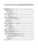
Page 4: ...ont panel 5 3 2 Indicator description 5 3 3 Interface description 6 Chapter 4 Device Settings 7 4 1 DIP switch description 7 4 1 1 The location of the DIP switches 7 4 1 2 DIP switch description 7 4 1...

Page 5: ...Release Notes Date of Release Manual Version Revisions 20071119 200706 REV A...

Page 6: ...le is intact and is connected to the transmitter Do not attempt to adjust the laser drive current Do not use broken or unterminated fiber optic cables connectors or look straight at the laser beam The...

Page 7: ...stricted access area i e an area where access is authorized only to qualified service and maintenance personnel Make sure that the DC supply is electrically isolated from any AC source and that the in...

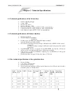
Page 8: ...nd duplex mode selectable The maximal Ethernet data frame length in support is 1784 bytes For Ethernet interface working in full duplex mode IEEE802 3x flow control is supported For Ethernet interface...

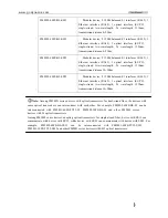
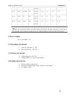
Page 9: ...dular device 2 120 balanced E1 interfaces RJ 45 1 Ethernet interface RJ 45 1 optical interface SC PC single strand two wavelength Tx wavelength 1550nm transmission distance 10 50km LNote Among FM280X...

Page 10: ...x mode back pressure flow control is supported Auto MDI MDIX function in support of Auto MDI MDIX this function will become ineffective if the Auto negotiation function of the interface is disabled Ot...

Page 11: ...ion distance in typical optical fiber condition The transmission distance that can be realized depends on the factual status of the network 2 4 Power supply Power consumption 3W 2 5 Operating environm...

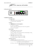
Page 12: ...ce indicator ON the Ethernet cable is correctly connected Flickering the Ethernet cable is well connected and there is data transmitting or receiving OFF the Ethernet cable is not well connected 100M...

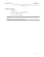
Page 13: ...description 2 E1 balanced interface 1 RJ 45 interface provides 2 lines of 120 balanced E1 signal E1 1 pin 1 and 2 output pin 4 and 5 input E1 2 pin 7 and 8 output pin 3 and 6 input LNote Please be sur...

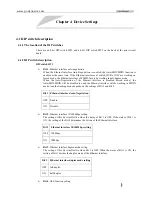
Page 14: ...forced mode the Auto MDI MDIX will be disabled too and the Ethernet interface will be working in MDIX mode And the working mode depends on the settings of Bit 2 and Bit 3 Bit 1 Ethernet interface Aut...

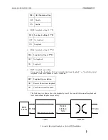
Page 15: ...ng Users can set the loopback of E1 to remote bidirectional loopback or local bidirectional loopback when the loopback of the E1 is enabled Bit 7 Loopback type selection OFF Remote bidirectional loopb...

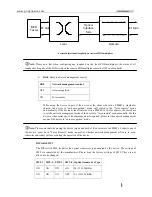
Page 16: ...t side is in a FM002 16 16 slot chassis the users have to set the network management mode of the device to force remote mode manually For the device at the central site if local management is required...

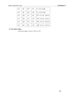
Page 17: ...1310 Tx Rx ON ON OFF OFF S3 1550 Tx Rx ON OFF ON ON SS13 1310 Tx 1550 Rx ON OFF ON OFF SS15 1550 Tx 1310 Rx ON OFF OFF ON SS23 1310 Tx 1550 Rx ON OFF OFF OFF SS25 1550 Tx 1310 Rx 4 1 3 Default Setting...

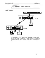
Page 18: ...RCMS2802 60FE BL ALM L R LPR COL ACT STA 1 2 3 4 5 6 7 8 9101112 HS1 HS2 OK1 OK2 PS CONSOLE PC E1 E1 Device E1 E1 Device Client Site CO Site As is shown in the figure above FM2802 60FE BL can be appl...

Page 19: ...form 6 2 Network management query The following information can be queried on the network management platform Local device version Local remote optical interface alarm Local remote device model Local...

Page 20: ...r E1 cable users can choose 22AWG or 24AWG twisted pair The E1 interfaces of FM2802 60FE BL are 120 balanced E1 interfaces Please check the type pin definition and impedance of the E1 interface of the...

Page 21: ...the optical interface are well connected 7 2 3 Device electrifying Please fix the module properly in the chassis before turning ON the power supply After electrifying the power supply status indicator...

Page 22: ...ng Remote optical interface Rx alarm Please check whether the fiber is well connected to the Rx of the remote optical interface and whether the Tx and Rx of the remote optical interface have been inco...

Page 23: ...Web http www godynamix com Email support dynamix ua...

Reviews: