background image


121 – 18799 AIRPORT WAY, PITT MEADOWS, BC, CANADA, V3Y 2B4


PHONE: 604-465-0009


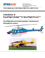
DynaNav Installation Manual 

Overview of System 

The DynaFlight-AirAgII™ system is a GPS based electronic guidance and data management system specifically 
designed as a tool for the pilot to fly parallel swath guidance for the application of seeds, fertilizer and chemicals for 
farm and forestry applications. It also gives guidance to return back to the job to continue his application after refill. 
The system automatically senses spray on and spray off for recording and displaying the real time map of the 
application and displays this to the pilot in his heads up display. The system comes with a built in satellite 
differential. 

Mounting  

GPS Antenna 

Overview 

As the GPS antenna has two functions, one, to view the full constellation of orbiting satellites and two, to 
view the geo-stationary differential broadcast satellite positioned over the equator, the antenna should have 
as much visibility of the full sky as possible. 

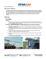
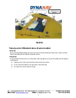
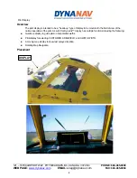
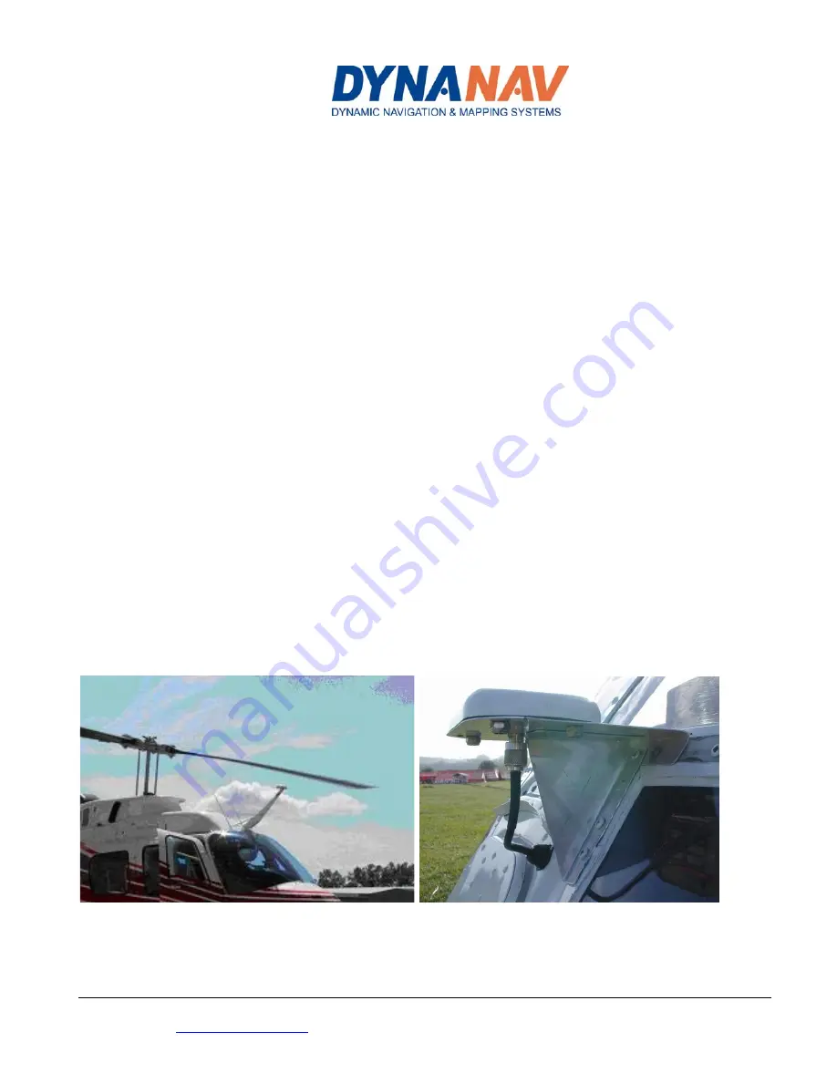
Placement – IMPORTANT!! Make sure that the GPS Antenna is bonded to the Airframe. 

The GPS antenna should be mounted on top of the aircraft/helicopter and should take into consideration 
the following. See figures 1, & 2: 

„


On helicopters, mount the antenna as far forward on the top as possible while keeping the antenna as flat to 
the horizon as possible. This is to keep it away from the rotor mast as much as possible as well as lead the 
pilot to the spot. 

„


The antenna should be mounted high enough to see as much of the sky above and around so as the 
fuselage does not block the signal and as far forward as possible. 

„


Mounting on the tail would be a last resort and should only be done if Laser Gyro option is installed in the 
DynaFlight. 

„


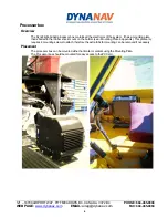
Keep as far away from transmitting antennas as possible (at least 12 inches) If this is not possible, please 
contact DynaNav for recommendations.  


WEB PAGE: 

www.dynanav.com

 EMAIL:

 airag@dynanav.com


FAX: 604-465-0084


2

Summary of Contents for DynaFlight-AirAgII

Page 1: ...LPFULHINTS ON DynaNav Systems Inc 121 18799 Airport Way Pitt Meadows BC Canada V3Y 2B4 www dynanav com Installationof DynaFlight AirAgII DynaFlight Forest DynaFlightAirborneAerialApplication Guidance...

Page 2: ...___6 Control Grip or Switches ________________________________________________________________________________7 Overview _______________________________________________________________________________...

Page 3: ...erential broadcast satellite positioned over the equator the antenna should have as much visibility of the full sky as possible Placement IMPORTANT Make sure that the GPS Antenna is bonded to the Airf...

Page 4: ...erential antenna has to view the ground based broadcast antenna the antenna should be outside the aircraft and have visibility of this base antenna Placement The ideal location for this antenna is on...

Page 5: ...he rubber shock mount on the bottom see Mounting Plate in appendix This plate only requires 4 mounting screws to attach therefore the extra tabs for mounting can be removed if necessary Placement The...

Page 6: ...of the normal operation of the pilot As such this DynaViz display has multiple functions including the following Guidance display to guide pilot on his parallel swaths Pilot display for selecting CUST...

Page 7: ...ndividual pilot needs be sure the bottom plate is mounted to allow for individual pilot needs tall or short The front of the screen should be oriented to front of helicopter aircraft to give guidance...

Page 8: ...d to the dual interface box to sense spray on off or other actions Placement If the grip cyclic or collective have a spare Top Hat switch it can be wired directly to the connector on the Dual Relay bo...

Page 9: ...AIL airag dynanav com FAX 604 465 0084 8 Collective Switch FIGURE 3 Product features With the grip or collective switch box in the pilots hands the pilot will be able to change job functions while obs...

Page 10: ...ches on the Spray Boom make sure the pressure is well within the range of the normal boom pressure for spraying The Cessna P N S 3010 1 Hobbs pressure switch can be adjusted to the right pressure You...

Page 11: ...t for helicopters for intuitive operator input Software file of Installation and Operations manual and quick reference user guide GPS Engine is sub meter with less than 0 1 second latency and presente...

Page 12: ...121 18799 AIRPORT WAY PITT MEADOWS BC CANADA V3Y 2B4 PHONE 604 465 0009 DynaViz Display Wiring WEB PAGE www dynanav com EMAIL airag dynanav com FAX 604 465 0084 11...

Page 13: ...121 18799 AIRPORT WAY PITT MEADOWS BC CANADA V3Y 2B4 PHONE 604 465 0009 DB 2 1224 4 Dual Relay Box and Power Input Plug WEB PAGE www dynanav com EMAIL airag dynanav com FAX 604 465 0084 12...

Page 14: ...121 18799 AIRPORT WAY PITT MEADOWS BC CANADA V3Y 2B4 PHONE 604 465 0009 I O Control Box Wiring Diagram WEB PAGE www dynanav com EMAIL airag dynanav com FAX 604 465 0084 13...

Page 15: ...121 18799 AIRPORT WAY PITT MEADOWS BC CANADA V3Y 2B4 PHONE 604 465 0009 WEB PAGE www dynanav com EMAIL airag dynanav com FAX 604 465 0084 14...

Page 16: ...121 18799 AIRPORT WAY PITT MEADOWS BC CANADA V3Y 2B4 PHONE 604 465 0009 TopHat Switch Layout WEB PAGE www dynanav com EMAIL airag dynanav com FAX 604 465 0084 15...

Page 17: ...121 18799 AIRPORT WAY PITT MEADOWS BC CANADA V3Y 2B4 PHONE 604 465 0009 Mounting PlateAssembly Drawings WEB PAGE www dynanav com EMAIL airag dynanav com FAX 604 465 0084 16...

Page 18: ...1 SHEET 1 of 1 REVISION 4 DB2 1224 4 INTEGRATED FLIGHT GUIDANCE INSTRUMENT BROWN RED BLACK ORANGE BLUE GREEN YELLOW PURPLE GREY WHITE E U BB FF EE DD CC Y Z AA RELAY CONTROL LOGIC 1 5 VOLTS COMMON GND...

Reviews: