

730
– 11731 BAYNES ROAD, PITT MEADOWS, BC, CANADA, V3Y 2B4
PHONE: 604-465-0009
EMAIL:
airag@dynanav.com
FAX: 604-465-0084
2
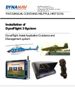
DynaNav Installation Manual
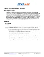
Overview of System
The DynaFlight-3
™ system is a GPS based electronic guidance and data management system specifically
designed as a tool for the pilot to fly Parallel Swath Guidance, Free Form Navigation and Live Moving Map for the
application of seeds, fertilizer and chemicals for farm and forestry applications. It also gives unlimited navigation
points including automatic Last Sprayed Point to return back to continue his application after refill. The system
automatically senses spray on and spray off for recording and displaying the real time map of the application and
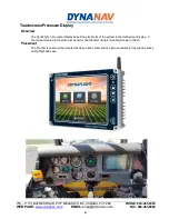
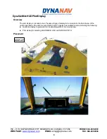
displays this to the pilot in his Heads-Up Display. Note: we have the DynaViz graphical display that we refer to as a
Mini-HUD but you do not see through it, however, it has a low profile, no different than a lightbar, to not block the
outside view. We are now releasing a true Heads Up Display that you see through the Combiner lens and the
image is projected way out in front of the display. Keep your eye out for this
– pun intended.
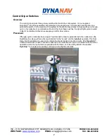
Mounting
GPS Antenna
Overview
As the GPS antenna has to view the full constellation of orbiting satellites and as such the antenna should
have as much visibility of the full sky as possible.
Placement
– IMPORTANT!! Make sure that the GPS Antenna is bonded to the Airframe.
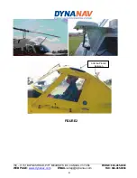
The GPS antenna should be mounted on top (not the bottom) of the aircraft/helicopter and should take into
consideration the following. See figures 1, & 2:
◼
On helicopters, mount the antenna as far forward on the top as possible. This is to keep it away from
the rotor mast as much as possible as well as lead the pilot to the spot.
◼
The antenna should be mounted high enough to see as much of the sky above and around so as the
fuselage does not block the signal and as far forward as possible.
◼
Mounting on the tail should only be done if Laser Gyro option is installed in the DynaFlight to correct the
position.
◼
Keep as far away from transmitting antennas as possible (at least 12 inches) If this is not possible,
please contact DynaNav for recommendations.
◼
For fixed wing aircraft, if the antenna can be mounted as far forward as possible without being on the
engine cowls, and of course on the centerline of the aircraft.