1.
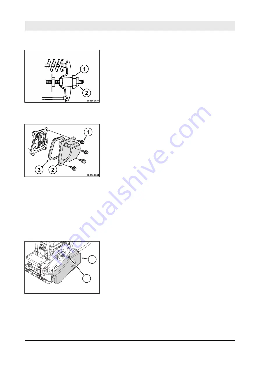
Hold the hexagon nut (1) on the rocker arm and loosen
counter nut (2).
2.
Adjust the hexagon nut, until the feeler gauge can be
inserted and pulled out with little resistance after retightening
the counter nut.
1.
Install the valve cover (2) with a new seal (3).
2.
Tighten the fastening screws (1) evenly.
3.
After a short test run, check the engine for leaks.
8.8.3 Replacing the V-belt
Protective equipment:
n
Working clothes
n
Safety shoes
n
Protective gloves
1.
Park the machine safely
Chapter 6.5 „Parking the machine
in secured condition“ on page 62
.
2.
Allow the engine to cool down.
3.
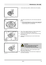
Loosen the fastening screws (2) and remove the V-belt guard
(1).
Adjusting the valve clearance
Fig. 68
Final work
Fig. 69
B-834-0144
1
2
Fig. 70
Maintenance – Annually
DFP9
82
Summary of Contents for DFP9
Page 2: ...2...
Page 6: ...Table of contents DFP9 6...
Page 7: ...1 Introduction Introduction DFP9 7...
Page 11: ...2 Technical data Technical data DFP9 11...
Page 15: ...3 Concerning your safety Concerning your safety DFP9 15...
Page 38: ...Concerning your safety Signage DFP9 38...
Page 39: ...4 Indicators and control elements Indicators and control elements DFP9 39...
Page 45: ...5 Checks prior to start up Checks prior to start up DFP9 45...
Page 52: ...Checks prior to start up Checking the water level topping up DFP9 52...
Page 53: ...6 Operation Operation DFP9 53...
Page 64: ...Operation Parking the machine in secured condition DFP9 64...
Page 65: ...7 Loading transporting the machine Loading transporting the machine DFP9 65...
Page 69: ...8 Maintenance Maintenance DFP9 69...
Page 100: ...Maintenance As required DFP9 100...
Page 101: ...9 Troubleshooting Troubleshooting DFP9 101...
Page 107: ...10 Disposal Disposal DFP9 107...
Page 109: ...11 List of special tools List of special tools DFP9 109...
Page 111: ......
Page 112: ......


