background image

OPERATION & MAINTENANCE

Paver Finisher
F1800C 
Type 910

03-1019

4812076575

Summary of Contents for F1800C

Page 1: ...OPERATION MAINTENANCE Paver Finisher F1800C Type 910 03 1019 4812076575...

Page 2: ...www dynapac com...

Page 3: ...incorrect usage 12 A Correct use and application 1 B Vehicle description 1 1 Application 1 2 Description of assemblies and functions 2 2 1 Vehicle 3 Construction 3 3 Danger zones 7 4 Safety devices 8...

Page 4: ...ing on hands and arms 33 7 5 Electromagnetic compatibility EMC 33 C10 18 Transportation 1 1 Safety regulations for transportation 1 2 Directing of the vehicle 2 3 Transportation on low bed trailers 3...

Page 5: ...led display Error Messages With Travel Drive Stop 13 Detailed display Vehicle Warning Messages 14 Detailed display Engine Error Messages 15 Info menu 16 Display of the following information 16 Display...

Page 6: ...justment 30 Push roller crossbar adjustable 31 Push roller damping hydraulic o 32 Fire extinguisher o 33 First aid kit o 33 Rotary beacon o 34 Illuminated balloon o 35 Installation and operation 36 Ma...

Page 7: ...her or screed 31 E10 18 Set up and modification 1 1 Special notes on safety 1 2 Distribution auger 3 2 1 Height adjustment 3 2 2 Auger width extension and material shaft with protective cover optional...

Page 8: ...ngine air filter 4 11 Engine cooling system 5 12 Engine drive belt 6 14 F60 18 Maintenance hydraulic system 1 1 Maintenance hydraulic system 1 1 1 Maintenance intervals 4 1 2 Points of maintenance 6 H...

Page 9: ...stem 1 3 Bearing points 2 7 F100 Tests stopping 1 1 Tests checks cleaning stopping 1 1 1 Maintenance intervals 2 2 General visual inspection 3 3 Check that the bolts and nuts fit firmly 3 4 Inspection...

Page 10: ...on diesel fuel 4 2 2 Drive engine TIER III o fuel specification 4 2 3 Drive engine TIER IV o fuel specification 4 2 4 Engine lubricating oil 5 2 5 Cooling system 5 2 6 Hydraulic system 5 2 7 Pump dis...

Page 11: ...xample Page B 2 is the second page of chapter B These operating instructions cover various vehicle options Make sure that during op eration and maintenance work the description appropriate to the vehi...

Page 12: ...sible for compliance with the resulting regulations and measures A The following warnings prohibitive symbols and instructive symbols indicate dangers for persons the vehicle and the environment due t...

Page 13: ...esult in fatal or se vere injuries unless the corresponding actions are taken Caution Indication of a possible danger that result in moderate or mi nor injuries unless the corresponding actions are ta...

Page 14: ...tched off Warning on dangerous electrical voltage m All maintenance and repair work on the screed s electrical system must always be carried out by an electrician Warning on suspended loads m Never st...

Page 15: ...V 5 Warning on danger of falling Warning on dangers posed by batteries Warning on hazardous or irritating substances Warning on substances which constitute a fire hazard Warning on gas bottles...

Page 16: ...tart engine drive Maintenance and repair work may only be carried out with the diesel engine shut down Spraying with water is prohibited Extinguishing with water is prohibited Unauthorised maintenance...

Page 17: ...ggles to protect your eyes Wear suitable head protection Wear suitable hearing protection to protect your hearing Wear suitable safety gloves to protect your hands Wear safety shoes to protect your fe...

Page 18: ...Hydraulic oil Diesel fuel Coolant Cleaning liquids must not get into the soil or sewer system during cleaning maintenance and repair work Substances must be caught stored transported and brought to pr...

Page 19: ...c umentation A For example the maintenance instructions of the engine manufac turer m Description depiction applicable when equipped with gas heater m Description depiction applicable when equipped wi...

Page 20: ...cified in the valid regulations and amend ments together with harmonised standards and other valid provisions 3 Guarantee conditions A The guarantee conditions are included in the scope of supply of t...

Page 21: ...ting range of the machine caused by wrong or improper use of the machine defective or missing safety devices use of the machine by untrained uninstructed staff defective or damaged parts incorrect tra...

Page 22: ...he machine includes presence in the danger zone of the machine transporting persons leaving the operator s platform while the machine is operating removing protection or safety devices starting and us...

Page 23: ...e meaning of these operating instructions is defined as any natural or legal person who either uses the paver finisher himself or on whose behalf it is used In special cases e g leasing or renting the...

Page 24: ...A 2...

Page 25: ...he Dynapac F1800C paver finisher is a paver finisher with a caterpillar drive which is used for paving bituminous mixed material roll down or lean mixed concrete track laying ballast and unbound miner...

Page 26: ...hickness 6 t Traction roller 7 t Crossbeam pull bar 8 t Paving thickness indicator 9 t Crossbeam 10 t Travel drive of the caterpillar drive 11 t Auger 12 t Screed 13 t Operator s platform 14 t Operati...

Page 27: ...conditions The operation of the paver finisher is considerably facilitated by the automatic mate rial handling system the independent travel drives and the clearly structured operat ing components an...

Page 28: ...hese hydraulic motors drive the caterpillar chains via planetary gears that are mounted directly inside the drive units of the caterpillar chains Steering system operator s platform The independent hy...

Page 29: ...dure the transfer amount is reg ulated fully automatically The drive is reversible Augers The augers are driven and actuated independently from the conveyors The left hand and the right hand half of t...

Page 30: ...e control system Crossbeams screed lifting device The screed lifting device is used to lift the screed for the paving conditions and during transportation This takes place by hydraulic means by actuat...

Page 31: ...e operator and the screed personnel are allowed on the vehicle or in the danger zone The vehicle operator and screed personnel must keep to the respective driver s seats Make sure that there is no one...

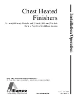
Page 32: ...B 8 4 Safety devices 5 7 11 3 1 2 9 12 10 10 8 4 5 6 7...

Page 33: ...f these devices at regular intervals A Functional descriptions for the individual safety facilities can be found in the following chapters Item Designation 1 Hopper transport safeguard 2 Crossbeam loc...

Page 34: ...ical data standard configuration 5 1 Dimensions all dimensions in mm A For screed technical data refer to the screed operating instructions R65 5270 2090 5020 1620 2590 2915 3600 3150 3040 1800 1200 2...

Page 35: ...ing your vehicle in an inclined position gradient slope lateral inclina tion which is above the specified limit value please consult the customer service de partment for your vehicle 5 3 Permissible a...

Page 36: ...screed attachments see the operating instruc tions for the screed Paver finisher without screed approx 8 9 Paver finisher with screed V3500 approx 10 5 With extension parts for max working width addi...

Page 37: ...paving width with cut off shoe fully variable hydr adjustment up to Maximum paving widths with extension parts V3500TV 1 75 0 7 3 50 4 7 m Transport speed 0 4 km h Operating speed 0 25 m min Paving h...

Page 38: ...engine Performance 54 KW 73 PS at 2200 rpm Fuel consumption full load Fuel consumption 2 3 load 14 l h 9 3 l h Fuel tank capacity See chapter F Make type Deutz TD 2 9 L4 Version 4 cylinder diesel eng...

Page 39: ...ight centre 520 mm Minimum inlet height outside 605 mm Hopper width outside open 3400 mm Type Dual conveyor belt Width 2 x 350 mm Conveyors Left and right auger separately controllable Drive Hydrostat...

Page 40: ...ible temperature ranges Special functions At standstill Screed stop Levelling system Mechanical grade control Optional systems with and without slope control On board voltage 24 V Batteries 2 x 12 V 7...

Page 41: ...r of injuries Never remove any warnings or information signs from the vehicle Damaged or lost warning or information signs must be replaced immediately Make yourself familiar with the meaning and posi...

Page 42: ...B 18 22 21 22 21 22 21 8 52 4 5 72 6 50 2 1 28 29 30 3 33 32 31 3 20 60 12 25 10 26 9 23 6 11 27 24...

Page 43: ...B 19 71 70 40 41 42 xxxxxxxxxxxxxxxxx 7 7 51 53 73...

Page 44: ...gine and re move the ignition key before perform ing any maintenance and repair work If the drive engine is left running or func tions are switched on this can cause se vere to fatal injuries Switch t...

Page 45: ...enance instructions 8 Caution Danger from incorrect towing Vehicle movements can cause severe to fatal injuries The traction system brake must be re leased before towing Always observe the operating i...

Page 46: ...cle forwards in reverse at transport speed Driving the vehicle when standing up without the seatbelt fastened can cause severe to fatal injuries Always observe the operating instruc tions 12 Maintenan...

Page 47: ...only permitted at these lifting points 22 Lashing point Lashing the machine is only permitted at these points 23 Main battery switch Position of the main battery switch 24 Diesel fuel Position of the...

Page 48: ...Position of the drainage point 28 Engine coolant Position of the filling and control point 29 Hydraulic oil Position of the filling point 30 Hydraulic oil level Position of the control point 31 Hydrau...

Page 49: ...B 25 6 3 CE marking No Pictogram Meaning 33 Gear oil drainage point Position of the drainage point No Pictogram Meaning 40 CE sound output level...

Page 50: ...Instructive symbols prohibitive symbols warning symbols No Pictogram Meaning 50 Wear ear protectors 51 Do not spray the area or component with water 52 Warning on dangers posed by batteries 53 First...

Page 51: ...mation Avoid contact with the human body also avoid inhaling the vapours and seek med ical advice if feeling unwell N Environmentally hazardous sub stance May cause immediate or delayed danger to the...

Page 52: ...ation 71 Attention Danger of high voltage in vehicle electrical system Disconnect batteries and electronics dur ing welding work or when charging the batteries or use a service watchdog D978000024 in...

Page 53: ...Designation 1 Paver finisher type 2 Year of construction 3 Operating weight incl all extension parts in kg 4 Maximum permitted total weight in kg 5 Max permissible load on the front axle in kg 6 Max p...

Page 54: ...B 30 6 8 Explanation of 17 digit PIN serial number A Manufacturer B Family Model C Code letter F Serial number 10002014JHG002076 A B C F...

Page 55: ...e type plate 1 is affixed on top of the engine The type plate states the engine type serial number and engine data Please state the engine number of the engine when ordering spare parts A See also ope...

Page 56: ...the paver finisher was measured under free field condi tions according to EN 500 6 2006 and ISO 4872 Sound pressure level at the operator s position at the height of the head LAF 87 0 dB A Sound capa...

Page 57: ...nts of the EMC Directive 2004 108 EC Interference emission according to DIN EN 13309 35 dB V m for frequencies of 30 MHz 1GHz measured at a distance of 10 m 45 db V m for frequencies of 30 MHz 1 GHz m...

Page 58: ...B 34...

Page 59: ...rmany gas bottles must not be transported on the paver finisher or on the screed Disconnect the gas bottles from the gas system and protect them with their caps Use a separate vehicle to transport the...

Page 60: ...as banksmen by the company and who can be expected to reliably perform the tasks assigned to them High visibility clothing must be worn The banksman and vehicle driver must have made themselves famil...

Page 61: ...be taken into consideration when selecting the attachment and loading equipment 3 1 Preparations Prepare the paver finisher for transportation see chapter D Remove all overlaying or loose parts from f...

Page 62: ...the hopper lids Engage both hopper transport safeguards Lift the screed Insert the transportation safeguards of the screed Fully extend the levelling cylinder Retract the screed parts until the screed...

Page 63: ...ble for securing loads positive fit force connection diagonal lashing etc in accordance with the specific transport vehicle m The low loader must have the necessary number of lashing points with a las...

Page 64: ...ke sure that there are no persons in the danger area during loading Use the work gear and low engine speeds to drive onto the low bed trailer Caution Possible collision of parts When driving up inclin...

Page 65: ...rmitted lashing force and load rating m Always tighten the lashing chains and straps hand tight 100 150 daN m Lashing equipment must be checked by the user for any signs of damage before use On detect...

Page 66: ...ther to the back of the vehicle Always heed the details regarding load distribution stipulated for the vehicle together with the centre of gravity of the paver finisher If the paver finisher has to be...

Page 67: ...ats under the screed across the whole width of the vehicle 2 and lower the screed Switch off the paver finisher Attach and secure the protective hood 3 to the operating panel Lower the roof and set th...

Page 68: ...on the paver finisher and on the low load trailer Fasten the lashing chains as shown m Shackles have to be used To ensure that lashing chains can be fitted securely on the left and on the right a shac...

Page 69: ...Fasten lashing chains m Diagonal lashing secures the paver finisher at the rear using the lashing points on the paver finisher and on the low load trailer Fasten the lashing chains as shown A Permissi...

Page 70: ...titled Protective roof Start engine Lift the screed to the transportation position Drive from the trailer at a low engine revs speed Park the paver finisher in a secure spot lower the screed and switc...

Page 71: ...on Possible collision of parts The following adjustments must be made before lowering the roof Both seat consoles pushed in Backrests and armrests of driver s seats tilted forwards Operating panel in...

Page 72: ...the roof has reached the upper or lower limit position Bolt 3 must be inserted in the corresponding hole on both sides of the roof Position 3a Roof raised Position 3b Roof lowered A The bolt must be...

Page 73: ...adjustment lever 4 to the Raise or Lower position Operate the pump lever 1 until the roof has reached the upper or lower limit position Bolt 3 must be inserted in the corresponding hole on both sides...

Page 74: ...loose parts from finisher and screed see also operating instructions for the screed Store these parts in a safe place f When screed is operated with the optional gas heating system Remove the gas bott...

Page 75: ...the hopper lids Engage both hopper transport safeguards Lift the screed Insert the transportation safeguards of the screed Fully extend the levelling cylinder Retract the screed parts until the scree...

Page 76: ...Set the fast slow switch to Hare if necessary Turn the preselector to zero Swivel the drive lever to maximum f The vehicle already advances slightly on deflecting the drive lever Adjust required vehic...

Page 77: ...ty is dependent on the screed which is mounted Danger from suspended loads Crane and or lifted vehicle can tip when lifted and cause injuries The vehicle may only be raised at the marked lifting point...

Page 78: ...the screed mounted is located in area 3 of the vehicle Secure vehicle wherever it is parked up Engage the transport safeguards Remove any attachments and extension parts from the paver finisher and t...

Page 79: ...ear to the four attachment points 1 2 m The max permissible attachment point load at the attachment points is 73 0 kN m The permissible load applies in the vertical direction m Make sure that the pave...

Page 80: ...ssure for releasing the traction system brakes is built up with the hand pump Release lock nut 2 screw threaded dowel 3 into pump as far as possible and secure with lock nut A From serial number 2281...

Page 81: ...completion of the towing process re store the initial status Attach the tow bar to the coupling 9 located in the bumper A The fastening point for the towing device is in the vehicle frame below the p...

Page 82: ...be secured in such a way that unauthorised persons or playing children cannot dam age the vehicle Pull off the ignition key and the main switch 1 and take it with you do not hide them somewhere on the...

Page 83: ...em from tilling over and rolling or sliding away f Roller type jacks must not be moved when under load f Chocks or supporting beams positioned so that they cannot be shifted or tilted must be adequate...

Page 84: ...C 10 18 26...

Page 85: ...e Always make sure during work that no one is endangered by the vehicle Ensure that all protective covers and hoods are fitted and secured accordingly Immediately rectify damage which as been ascertai...

Page 86: ...or conveying vehicle parts Rotating or conveying vehicle parts can cause severe to fatal injuries Do not enter the danger zone Do not reach into rotating or conveying parts Only wear close fitting cl...

Page 87: ...ons that can pose a hazard when the diesel engine starts up turning to the side conveying function of auger and conveyor prevent the engine from starting start inhibit when switched on or when set to...

Page 88: ...D 10 18 4 13 14 17 16 18 15 10 12 11...

Page 89: ...st be pulled out again 11 Engine speed adjuster Continuously variable engine speed setting if drive lever is extended Min setting Idling speed Max position Nominal speed A For paving select the rated...

Page 90: ...D 10 18 6 13 14 17 16 18 15 10 12 11...

Page 91: ...on 2 position Screed motion tamper vibration on travel drive on increase speed until the stop is reached A Use the preselector to set the maximum speed f The vehicle speed cannot be reduced to 0 with...

Page 92: ...D 10 18 8 13 14 17 16 18 15 10 12 11...

Page 93: ...matches the speed in m min during paving m The vehicle must not travel at max transport speed when the hopper is full f The vehicle speed cannot be reduced to 0 with the preselector The vehicle advanc...

Page 94: ...D 10 18 10 21 20...

Page 95: ...eft hopper lid Lower switch position Open left hopper lid f On actuation heed danger zones of moving parts of the vehicle 21 Open close right hopper Pushbutton function Upper switch position Close rig...

Page 96: ...D 10 18 12 23 22...

Page 97: ...screed Right switch position Retract left half of screed f On actuation heed danger zones of moving parts of the vehicle 23 Retract extend right screed Pushbutton function Left switch position Retrac...

Page 98: ...D 10 18 14 25 24...

Page 99: ...nder Lower switch position Extend left levelling cylinder f On actuation heed danger zones of moving parts of the vehicle 25 Retract extend right levelling cylinder Pushbutton function Upper switch po...

Page 100: ...D 10 18 16 26 27...

Page 101: ...capacity without material control via the limit switches f On actuation heed danger zones of moving parts of the vehicle 27 Right auger Operating mode AUTO OFF MANUAL Detent switch function Operating...

Page 102: ...D 10 18 18 28 29...

Page 103: ...en A The main function switch locks the conveying function f On actuation heed danger zones of moving parts of the vehicle 29 Reverse right auger Conveying direc tion inwards Pushbutton function manua...

Page 104: ...D 10 18 20 30 31...

Page 105: ...ery rate without material control via the limit switches f On actuation heed danger zones of moving parts of the vehicle 31 Right conveyor Operating mode AUTO OFF MANUAL Detent switch function Operati...

Page 106: ...D 10 18 22 32 33...

Page 107: ...en A The main function switch locks the conveying function f On actuation heed danger zones of moving parts of the vehicle 33 Reversing switch Right conveyor Pushbutton function The conveying directio...

Page 108: ...D 10 18 24 34 35...

Page 109: ...ed out A To prevent the screed from lowering during an interme diate stop drive lever in centre position the screed is hydraulically held in position via relief pressure and the counter pressure of th...

Page 110: ...D 10 18 26 36 37...

Page 111: ...witch position AUTO can also be put into operation with the control lever not swivelled by means of the Set up mode button 37 Tamper Operating mode AUTO OFF Detent switch function Upper switch positio...

Page 112: ...D 10 18 28 38...

Page 113: ...ically extend the push roller crossbar Switch position central OFF Lower switch position Retracting active by counterpressure A If the push roller crossbar has been pressed into the home position by t...

Page 114: ...D 10 18 30 39 40 41 42...

Page 115: ...working lights ON Lower switch position Front working lights OFF f Avoid dazzling other road users 41 Rear working lights ON OFF o Detent switch function Upper switch position Rear working lights ON L...

Page 116: ...D 10 18 32 44 43...

Page 117: ...vehicle turns to the left Steering turned to the right vehicle turns to the right A The function can only be activated in the working gear travel drive slow speed f When the vehicle turns persons and...

Page 118: ...D 10 18 34 45 46 47...

Page 119: ...ng process is continued on swivelling the drive lever out A On restarting the function is set to ON A Heed corresponding screen display 46 Set up mode Pushbutton function When the vehicle is stationar...

Page 120: ...D 10 18 36 47...

Page 121: ...nction for the paving process The conveying functions set to automatic conveyor and auger are switched on A Once the set material height is reached at the limit switches the conveying functions are sw...

Page 122: ...t right the function switches only control the corresponding function on the particular side of the machine m Important Do not disconnect remote controls with emergency stop button during op eration T...

Page 123: ...d to indicate when the ve hicle starts to move A The horn can also be used to communicate acoustical ly with the truck driver for material loading 92 Auger left right Operating mode AUTO OFF MANUAL De...

Page 124: ...D 10 18 40 90 91 92 94 93 95 96 96...

Page 125: ...switch position Operating mode MANUAL height adjustment is carried out using the corresponding function switches on the remote control or operating panel Lower switch position Operating mode AUTO heig...

Page 126: ...D 10 18 42...

Page 127: ...D 24 18 1 D 24 18 Operating the display...

Page 128: ...gned in the display area A1 A For orientation the corresponding symbol shows an opened menu in the status line B A To confirm an active opened menu the colour of the cor responding symbol changes from...

Page 129: ...dual displays can be found in the section Symbols for status warning and error messages Colour code Explanation RED error message Reports a serious fault that must be checked and rec tified immediatel...

Page 130: ...ions switched on with the operating panel are shown for confirmation in the display area A The function is activated when the corresponding symbol appears blue 1 Main function switch activated 2 Set u...

Page 131: ...The Home menu is open in the display Press button A to open the screed heater menu Press the plus minus button B C to activate the selected parameter to be adjusted A A blue frame appears around the...

Page 132: ...appears in the area which is activated for the adjustment Press button A until the blue frame is around the required adjustment parameter Press button B to activate the selected parameter to be adjus...

Page 133: ...lays Displays 1 Speed Paving tortoise Driving hare 2 Fuel gauge 3 Actual temperature of the screen heater C F A The display shows the average temperature of all screed sections 4 Actual diesel engine...

Page 134: ...ggering necessary particulate filter regeneration A Necessary regeneration is indicated by the regeneration warning sign 1a A Please heed the notes in the Terminal error messages section A When the fu...

Page 135: ...from particulate filter regeneration Improper particulate filter regeneration can cause severe to fatal injuries Keep the outlet of the exhaust pipe out of the reach of peo ple and of objects that can...

Page 136: ...ay A The menu for filter regeneration is only displayed for vehicles with corresponding exhaust gas aftertreatment 3 Engine coolant temperature C F 4 Engine operating hours h 5 On board voltage V Call...

Page 137: ...arameters 2 Average actual temperature of all screed sections C F A Direct adjustment of the nominal temperature by pressing the plus minus buttons 3 4 A Setting range 50 200 C A When the heater is sw...

Page 138: ...ehicle warning messages Open detailed display Vehicle Warning Messages 2 1 3 Number of engine error messages Open detailed display Engine Error Messages 3 1 A Possibly notify customer service of the s...

Page 139: ...ages in a table 1 Error code 2 Error description 3 Parameters see Bodas error list A If present the following page of the list is shown after a few seconds in each case Call up the following menus 4 V...

Page 140: ...le 1 Error code 2 Error description 3 Parameters see Bodas error list A If present the following page of the list is shown after a few seconds in each case Call up the following menus 4 Error Messages...

Page 141: ...error frequency A All error messages can be identified in the section Drive engine error codes A If present the following page of the list is shown after a few seconds in each case Call up the followi...

Page 142: ...tion 1 Software version of the vehicle 2 Software version of the display A If consultation with Technical Support is required for your vehicle always specify the software version Call up the following...

Page 143: ...in min 1 2 24hrs PM AM 2 Selection System Language English German 3 Selection Units of measurement Metric Imperial US Monitor brightness display and adjustment parameters 4 1 Daytime light 4 2 Nightti...

Page 144: ...l II Particular filter regeneration must be carried out as soon as possible The engine output may be automatically reduced under certain circumstances Indicator lamp flashes indicator lamp Engine malf...

Page 145: ...pipe out of the reach of people and of objects that can burn melt or explode f There may not be any people or objects with in a radius of 0 6 m of the exhaust outlet f There may not be any objects or...

Page 146: ...f fault the vehicle can temporarily continue to be operated or in the case of serious faults should be shut down immediately to prevent further damage from occurring Each fault should be rectified as...

Page 147: ...temperature The engine temperature is too high m The engine performance will be throttled down automatically Driving mode remains possible Stop the paver finisher drive lever to the cen tre position...

Page 148: ...ble errors see engine s operating instructions A This error is displayed together with Error Message Emergency mode active Vehicle error The control unit reports one or several malfunc tions that caus...

Page 149: ...D 24 18 23 2 1 Drive engine error codes A If a fault is detected on the engine this is shown by the corresponding indication 1 in the display 1...

Page 150: ...oding A If present the following page of the list is shown after a few seconds in each case m It may be possible to continue operating the vehicle depending on the severity of the error The error shou...

Page 151: ...D 24 18 25 Example...

Page 152: ...ry engine shut down Display SPN 157 FMI 3 OC 1 Cause Cable break on sensor for rail pressure Effect Engine shut down Frequency Fault occurs for the 1st time m Notify customer service of the error numb...

Page 153: ...18 27 3 Menu structure of the setting and display menus The following illustration shows the menu structure and serves to simplify operation and the procedure in the case of various settings and disp...

Page 154: ...D 24 18 28...

Page 155: ...lling from the vehicle which can cause severe to fatal injuries During operation the operator must be at the intended driver s seat and be seated properly Never jump onto or off a moving vehicle Keep...

Page 156: ...n Possible collision of parts The following adjustments must be made before lowering the roof Both seat consoles pushed in Backrests and armrests of driver s seats tilted forwards Operating panel in l...

Page 157: ...the roof has reached the upper or lower limit position Bolt 3 must be inserted in the corresponding hole on both sides of the roof Position 3a Roof raised Position 3b Roof lowered A The bolt must be i...

Page 158: ...adjustment lever 4 to the Raise or Lower position Operate the pump lever 1 until the roof has reached the upper or lower limit position Bolt 3 must be inserted in the corresponding hole on both sides...

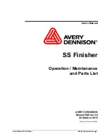
Page 159: ...D 30 18 5 Control platform telescoping seat consoles 10 B A B 11 6 4 5 2 8 A 9 7 12...

Page 160: ...in one of the intended detent positions Raise lower the operating panel Release clamping lever 6 lift or lower operating panel Tighten clamping lever 6 in required position Steering wheel inclination...

Page 161: ...onsoles increase the basic width of the paver finisher f If the seat consoles are moved ensure that there is no one in the danger area f Only adjust the operating position whilst the vehicle is statio...

Page 162: ...andle 3 with the latch pulled 2 To close the front window pull the latch 2 and pull the sliding frame at the handle 3 Risk of crushing hands When closing the spring loaded front window there is a risk...

Page 163: ...lable to the left and right of the protective roof to protect the driver for example when the seat console is extended Pull the latch 6 and extend the sunshade Set the latches in one of the intended d...

Page 164: ...vidually adjusted Raise the button to adjust the inclination The seat surface in clines to the desired position by simultaneously loading or relieving it Armrest inclination 6 The armrest s longitudin...

Page 165: ...at height adjustment 4 The seat height can be individually adjusted Turn the handle in the desired direction to adjust the seat height Backrest adjustment 5 The backrest inclination can be continuousl...

Page 166: ...0 18 12 Fuse box The terminal box which contains all fus es and relays etc is located beneath the central control platform floor panel A An assignment plan for fuses and relays can be found in chapter...

Page 167: ...ding to the instructions see section Starting the paver finisher ex ternal starting starting aid Main battery switch The main battery switch separates the current circuit from the battery to the main...

Page 168: ...y open dan ger during transportation Screed lock mechanical A The screed locks must additionally be engaged on both sides of the vehicle pri or to transportation with the screed lifted f Transportatio...

Page 169: ...he reading position the scale 1 can be raised and lowered again in one of the adjacent locating bores 2 The pointer 3 can be swivelled to differ ent positions using the locking knob 4 m The scale 1 an...

Page 170: ...D 30 18 16 Auger lighting o A Two swivelling headlights 1 are located at the back of the vehicle for illuminating the auger compartment They are engaged together with the working lights 1...

Page 171: ...D 30 18 17 LED working light o There are two LED spotlights 1 at the front and rear of the vehicle f Always align the working lights to avoid dazzling the operating personnel or oth er road users 1 1...

Page 172: ...kwise lifts the auger Actuate the ratchet lever 2 Set the desired height by alternatingly actuating the left and right ratchets The current height can be read at the scale 3 Hydraulic height adjustmen...

Page 173: ...rod increases the basic width of the paver finisher f If the sensor rod or sensor rod extension are used ensure that there is no one in the vehicle s danger area A The sensor rod is adjusted when the...

Page 174: ...adjustment to the required length You can also change the angle by swivelling the joint 5 m Tighten all assembly parts properly after setting up m During transportation the sensor rod must be swivelle...

Page 175: ...Remove the spray 1 from its bracket Build up pressure by actuating the pump lever 2 The pressure is indicated on the ma nometer 3 Actuate the manual valve 4 to spray On completion of work secure the...

Page 176: ...here The hose is automatically retracted into the guide after pulling and dis charging again Actuate button 3 to activate and de activate the pump The indicator lamp 4 lights up when the emulsion pump...

Page 177: ...the rele vant half of the conveyor The conveyors should stop when the material has roughly reached the area below the auger tube A This requires that the auger height has been adjusted correctly see...

Page 178: ...sor s angle After adjusting retighten all mounting parts properly A The connection cables 4 are connected to the relevant sockets on the remote con trol bracket A The sensors should be adjusted so tha...

Page 179: ...set the sensor height the deacti vation point loosen the star handles 4 and adjust the linkage to the re quired length After adjusting retighten all mounting parts properly A The connection cables ar...

Page 180: ...A socket 1 is located behind the left right seat consoles Additional working lights can be con nected here for example Right seat console 12V socket Left seat console 24V socket A Voltage is present w...

Page 181: ...p on the oper ator s platform m The pumping interval adjusted in the facto rymustbemodifiedto thepavingsituation A Changing the duration of lubrication and breaks may be necessary when laying mineral...

Page 182: ...he pressure for the screen con trol with paving stop floating stop with relief A Isengagedautomatically with paving stop Pressure adjustment with valve 1 A Lock the valve with the corresponding nut af...

Page 183: ...rer 1 up and se cure in the uppermost position with a shackle 2 To lower the lane clearer it must be lifted a little and the shackle 2 must be swivelled back A The blade s level above the ground is ad...

Page 184: ...locks 2 for eccentric adjustment Swivel screed to the desired position using the lever 3 and engage the locking knob again A If the levelling unit is connected to a height controller this has the func...

Page 185: ...f the crossbar Remove insert plate 4 Remove bolt 5 Move the push roller crossbar as far as it will go to the front rear position A Shift the push roller crossbar at the towing eye or use a suitable as...

Page 186: ...30 18 32 Push roller damping hydraulic o A Push roller damping hydraulically absorbs the shocks between the material truck and paver finisher Activate the function on the operating panel as necessary...

Page 187: ...nel must be fa miliarised with operation of the fire extin guisher 1 A Observe the inspection interval for the fire extinguisher First aid kit o f Any dressings that have been used must be replaced im...

Page 188: ...secure with a wing bolt 1 Raise the bracket 2 swivel to the outer position and allow to engage there Slide the rotary beacon with the tube 2 out to the desired height and se cure with the clamping bo...

Page 189: ...of bridges and tunnels and the enlarged vehicle width f Always disconnect the power supply before working on the illuminated balloon f Never look directly in the balloon when it is switched on f The i...

Page 190: ...holding tube 5 and tighten the clamping bolt 6 Close the zip fastener in the balloon skin and smooth away any large wrinkles in the skin Guide the holding tube 5 into the premounted holder 1 and tigh...

Page 191: ...ts to clean the balloon skin Replacing the lamp Disconnect the power cable and open the zip fastener of the skin f Let lamp cool down completely m Always wear the supplied cotton glove to touch the la...

Page 192: ...D 30 18 38...

Page 193: ...rts Diesel fuel Engine oil and hydraulic oil lubricants Separator fluids emulsion and manual injector A full bottle of propane gas o Shovel and broom Scraper spatula for cleaning the auger and the hop...

Page 194: ...lighting must be provided when working at night Comply with all further information in these instructions and in the safety manual Danger of falling from the vehicle Entering and leaving the vehicle a...

Page 195: ...t stop immediately Steering The paver finisher must immediately follow every steering wheel movement in a precise manner Check straight ahead travel Horn on the operating panel on both remote controls...

Page 196: ...ecurely seated Screed transport safeguard When the screed is raised before transport make sure that the crossbeam lock is fixed correctly Hopper transport safeguard When the hopper is closed before tr...

Page 197: ...D 40 18 5 1 9 2 5 5 3 4 6 7 8...

Page 198: ...current drain on the battery Turn ignition key 3 to position 1 and wait for the preheat check 8 o to go off A The vehicle cannot be started if the indicator lamps are on Start inhibit 4 Emergency sto...

Page 199: ...D 40 18 7 1 9 2 5 5 3 4 6 7 8...

Page 200: ...hicle battery Then connect the negative ter minal C of the starting aid battery to the ground of the discharged vehicle e g to the engine block or to a bolt D on the vehicle frame f Do not connect the...

Page 201: ...he starting button 9 to start the engine Do not let the starter run permanently for more than 20 seconds then allow for a break of one minute A If the engine does not start and the Error message 5 ind...

Page 202: ...D 40 18 10 1 2 3 4 5 6...

Page 203: ...gine speed can be increased by switching on a conveying function Switch off the engine and determine the fault if the lamp does not go out For further possible malfunctions refer to the section Malfun...

Page 204: ...D 40 18 12 2 3 6 5 7 1...

Page 205: ...e levelling cylinders with the switch 5 A To extend the levelling cylinders levelling operating mode 6 must be switched to MANUAL on the remote controls Use switch 7 to adjust the screed to the basic...

Page 206: ...D 40 18 14 2 2 3 1 6 5 4...

Page 207: ...edium speed For driving carefully tilt the drive lever 3 forward or backward according to the drive direction desired Adjust the speed with the preselector 2 If necessary increase the engine speed wit...

Page 208: ...ed auger push roller with a separator fluid m Do not use diesel fuel as it dissolves the bitumen prohibited in Germany Screed heater system Switch on the screed heater approx 15 30 minutes depending o...

Page 209: ...rks To ensure straight paving a direction mark must be present or established road edge chalk lines or similar Slide the operating panel to the de sired side and secure it Adjust direction of travel i...

Page 210: ...D 40 18 18 A 1 3 2 4...

Page 211: ...ust the con veyor limit switches with the vehicle turned off until sufficient material is conveyed in front of the screed Filling function A The filling function can additionally be used to convey the...

Page 212: ...D 40 18 20 1 2 5 6 7 4 11 10 3 12 9 8...

Page 213: ...ve wheels as the screed tends to level an uneven ground The reference points for the layer thickness are the caterpillar chains or drive wheels The basic setting of the screed must be corrected when t...

Page 214: ...n the way Uniform material transport and distribution or supply to the screed may require cor rections to settings of the material switches for conveyor and auger A See the section Malfunctions when p...

Page 215: ...D 40 18 23 3 1 2...

Page 216: ...d out A To prevent the screed from lowering during an intermediate stop drive lever in centre position the screed is hydraulically held in position via relief pressure and the coun ter pressure of the...

Page 217: ...D 40 18 25 1 2 3...

Page 218: ...empty and create an edge like the end of a layer Set the drive lever 1 to the centre position During extended interruptions e g lunch break Set the drive lever 1 to the centre position and the speed...

Page 219: ...D 40 18 27 1 3 14 2 15 5 8 4 9 7 6 5 4 11 10 12 13 16...

Page 220: ...ystem off See screed operating instructions Switch the working and warning lights 13 to OFF Read and check the operating hour meter 14 to determine whether maintenance work must be performed see chapt...

Page 221: ...e long waves change in the material temperature demixing roller has stopped on the hot material roller has turned or roller speed has been changed too fast incorrect operation of the roller incorrectl...

Page 222: ...w screed extendable parts are incorrectly installed cold screed bottom plates are worn or warped screed is not operated in the floating position paver finisher speed is too high auger is overloaded ch...

Page 223: ...the suction line of the pump Seal or replace the connections Tighten or replace the hose clamps Oil filter is soiled Clean the filter if necessary replace the filter Conveyor or augers run too slowly...

Page 224: ...annot be lifted Oil pressure too low Increase the oil pressure Leaking seal Replace Screed relieving or charg ing is switched on Switch must be in the centre position Power supply interrupted Check fu...

Page 225: ...servo unit Insufficient supply pressure Check and adjust if necessary Check the suction filter replace the supply pump and the filter if necessary Drive shaft of hydraulic pumps or engines broken Repl...

Page 226: ...D 40 18 34...

Page 227: ...er into centre position and turn preselector controller to zero remove ignition key and battery main switch Protect lifted vehicle parts e g screed or hopper against lowering by means of mechanical sa...

Page 228: ...d void and can cause severe to fatal injuries Only use original spare parts and approved accessories After maintenance and repair work ensure that any dis mantled protective and safety devices are all...

Page 229: ...ncorrect height setting can result in the following problems during paving Auger too high Too much material in front of the screed material overflow When operating with larger working widths demixing...

Page 230: ...ise or anti clockwise direction Adjust the required height by actuating the ratchet 2 The current height can be read at the scale 3 Hydraulic height adjustment Adjust the required height by pressing t...

Page 231: ...itional auger segment 1 is fitted to the auger shaft Assembly Remove outermost screw connection 2 from the basic auger Remove plug 3 Fit the auger extension 1 to the corresponding side Fit screw conne...

Page 232: ...the crossbar Remove insert plate 4 Remove bolt 5 Move the push roller crossbar as far as it will go to the front rear position A Shift the push roller crossbar at the towing eye or use a suitable ass...

Page 233: ...hopper scrapers 1 must be adjusted on both hopper lids Loosen the mounting screws 2 Set a gap of 6 mm across the whole length of the scraper Retighten the mounting screws 2 properly f Risk of injury...

Page 234: ...the vehicle must be adjusted to the prevailing paving conditions e g positive or negative crowning etc Remove screws 2 Move guide plate to the required size basic setting 25mm Retighten the mounting s...

Page 235: ...ructions cover all work required for mounting setting up and extending the screed 4 Electrical connections Prepare or make the following electrical connections when the mechanical compo nents have bee...

Page 236: ...to install the cables Install the cables to rule out the risk of any damage to the cables m If the side shield is not connected the socket 4 has to be connected with the bridge plug 4a Other connectio...

Page 237: ...ure with a clamping lever 4 Connect the left or right sensor s con nection cable 5 to the intended re mote control bracket sockets A The connection cables are connected to the relevant sockets on the...

Page 238: ...osen the star handles 4 and adjust the linkage to the re quired length After adjusting retighten all mounting parts properly A The connection cables are connected to the relevant sockets on the remote...

Page 239: ...Ensure that maintenance and repair work is always only carried out by trained specialist staff All maintenance repair and cleaning work should only be carried out with the engine turned off Remove ig...

Page 240: ...ces Surfaces including those behind covering parts together with combustion fuels from the engine or screed heater can be very hot and cause injuries Wear your personal safety gear Do not touch hot pa...

Page 241: ...F 20 18 1 F 20 18 Maintenance review 1 Maintenance review 70 18 40 18 50 18 82 18 90 100 31 18 60 18...

Page 242: ...ting hours 10 50 100 250 500 1000 annually 2000 every 2 years 5000 20000 If necessary Conveyor F31 18 q q q Auger F40 18 q q q q q Engine F50 18 q q q q q q Hydraulic system F60 18 q q q q q q q Drive...

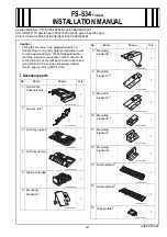
Page 243: ...F 31 18 1 F 31 18 Maintenance conveyor 1 Maintenance conveyor...

Page 244: ...and transport close both hopper lids and fit the correspond ing hopper transport safeguards When the vehicle is parked and during maintenance and transport raise the screen and fit the corresponding...

Page 245: ...If necessary 1 q Conveyor chain Check tightness q Conveyor chain Adjust tension q Conveyor chain Replace chain 2 q Conveyor drive drive chains Check chain tightness q Conveyor drive drive chains Adju...

Page 246: ...rial falls into the space be tween the chain and the sprocket If the chains are too slack it may get stuck in the protruding objects and be damaged Adjustment of chain tension A One adjusting screw is...

Page 247: ...iding the chains would lead to destruction of the drive wheels m If components have to be replaced as a result of wear the following components should always be replaced in sets Conveyor chain Conveyo...

Page 248: ...ain sag Move the chain If the tension has been set properly the chain must be able to move freely approx 10 15 mm To re tension the chains Unfasten mounting screws B and lock nut C slightly Adjust the...

Page 249: ...deflectors with new bolts A At the latest the conveyor plates B must be replaced when the wear limit of 5 mm in the rear area beneath the chain has been reached m If components have to be replaced as...

Page 250: ...F 31 18 8...

Page 251: ...F 40 18 1 F 40 18Maintenance auger assembly 1 Maintenance auger assembly...

Page 252: ...emove the ignition key before any maintenance work Comply with all further information in these instructions and in the safety manual Hot surfaces Surfaces including those behind covering parts togeth...

Page 253: ...Check tension q Auger drive chains Adjust tension q Augur drive chains Replace chains and chain sockets 2 q Augur box Check grease fill q Augur box Top up with grease q Augur box Change grease 3 q Se...

Page 254: ...00 1000 annually 2000 every 2 years 5000 If necessary 5 g g Outer bearing bolts Check tightening q Outer bearing bolts Tighten to correct torque 6 q Auger blade Check wear q Auger blade Replace auger...

Page 255: ...n both augers to the right and left In this case movement clear ance C at the augers outer circumference should be 3 4 mm f Risk of injury due to sharp edged parts To re tension the chains Release the...

Page 256: ...uger shaft or drive are worn The chains A have lengthened to such an extent that they can no longer be retightened m Chains and chain sprockets must al ways be replaced in sets A Your Dynapac customer...

Page 257: ...tity and quality a film of grease ad heres to the full length of both chains B Top up with grease if necessary Reinstall cover A Change grease A The grease should be changed regularly when proceeding...

Page 258: ...After reaching operating temperature check the gearbox for leaks m In case of visible leaks e g between the flange surfaces A of the drive auger shaft B or at the side cover C re placement of the seal...

Page 259: ...ally greasing the outer bearing points in or der to improve ventilation on greasing The outer rings must be properly se cured again after greasing A New bearings must be filled with 60 strokes of grea...

Page 260: ...uced and the blades B have to be replaced Remove the bolts C washers D nuts E and auger blade B f Risk of injury due to sharp edged parts m Auger blades must be installed play free the contact surface...

Page 261: ...y 1 Maintenance engine assembly m As well as this maintenance manual always also pay close attention to the mainte nance manual provided by the engine manufacturer All maintenance work and serv ice in...

Page 262: ...emove the ignition key before any maintenance work Comply with all further information in these instructions and in the safety manual Hot surfaces Surfaces including those behind covering parts togeth...

Page 263: ...lean the tank and system 2 q Engine lube oil system Check oil level q Engine lube oil system Top up oil q Engine lube oil system Change oil q Engine lube oil system Change oil filter 3 q Engine fuel s...

Page 264: ...filter Replaceair filter cartridge 5 q Engine cooling system Check radiator fins q q Engine cooling system Clean radiator fins q Engine cooling system Check level of the coolant q Engine cooling syste...

Page 265: ...0 50 100 250 500 annually 1000 annually 2000 every 2 years If necessary 6 q Engine drive belt Check drive belt q Engine drive belt Tighten drive belt q q Engine drive belt Replace drive belt Maintenan...

Page 266: ...stem cannot run dry and time consuming venting bleeding can therefore be avoided For filling with fuel Remove cover A Fill in fuel through the filling port until the required fill lever is achieved Re...

Page 267: ...heck the oil level when the finisher is in a horizontal position A The sensor rod is located at the front end of the engine m Too much oil in engine damages gas kets too little oil results in overheat...

Page 268: ...nserted during an oil change once the used oil has been drained out A The oil filter is located at the front end of the engine Use the maintenance flap for access Loosen the filter D using a filter wr...

Page 269: ...in the collecting vessel at regular in tervals or in response to an error mes sage from the engine control unit Put a suitable drip pan underneath Disconnect the electrical connection cable connection...

Page 270: ...lectric fuel feed pump Do not attempt to start the ve hicle while the fuel system is being bled to ensure that no error message is generated Ignition ON A The electronic fuel feed pump switches on for...

Page 271: ...the filter selected A Filter maintenance becomes necessary if Maintenance interval or Engine electronics service indicator Open the air filter lid Pull out the filter cartridge D and the safety cartr...

Page 272: ...tem is under pressure When opening there is a danger of scalding m Use only approved coolants A Observe the instructions in the chapter entitled Operating substances Remove the drain screw B on the ra...

Page 273: ...ary remove leaves dust or sand from the radiator A Observe engine s operating instructions Checking coolant concentration Check the concentration using a suitable tester hydrometer Adjust the concentr...

Page 274: ...transverse cracks in the belt are acceptable m In the event of longitudinal cracks which intersect with transverse cracks and damaged material surfaces belt re placement is necessary A Observe engine...

Page 275: ...F 60 18 1 F 60 18 Maintenance hydraulic system 1 Maintenance hydraulic system...

Page 276: ...Secure the vehicle to prevent it being switched on again Consult a doctor immediately if injured Comply with all further information in these instructions and in the safety manual Hot surfaces Surfac...

Page 277: ...n key before any maintenance work Secure the vehicle to prevent it being switched on again Let the hydraulic oil cool down A After depressurising begin slowly and carefully when opening the threaded c...

Page 278: ...tank Change oil and clean q Hydraulic oil tank Change ventilation filter 2 q Hydraulic oil tank Check maintenance indicator q q Hydraulic oil tank Change and vent the suction re turn flow hydraulic fi...

Page 279: ...p oil g q Pump distribution gear Change oil q Pump distribution gear Check bleeder q Pump distribution gear Clean bleeder 6 g q Hydraulic hoses Visual inspection g q Hydraulic system Leak test q Hydra...

Page 280: ...the side of the tank For filling with oil Remove cap B Fill in oil through the filler opening until the oil level rises to the centre of the sight glass A 5 mm Screw cap B on again A Regularly remove...

Page 281: ...n the oil drainage hose F opens the valve to let the oil drain out Place the end of the hose in the col lecting vessel and let the oil drain completely Unscrew the drainage hose and return the screw c...

Page 282: ...the sealing surfaces and O rings with clean operating fluid Fill the opened filter housing with hy draulic oil up to approx 2 cm below the top edge If the oil level drops replenish oil again A Slow oi...

Page 283: ...er cartridge Clean the filter housing Insert the new filter cartridge Replace the seal ring of the filter housing Turn on the filter housing by hand and tighten it using a wrench Start trial operation...

Page 284: ...ench A Put a vessel underneath to collect the draining oil Remove the screw in neck with strain er element D Shake any remaining oil out of the housing E into a vessel for used oil then clean the filt...

Page 285: ...glass A Screw in the filler screw B again m Make sure to clean the screw and the vi cinity of the drain bore Oil change Place the end of the oil drain port hose C in the collection container Remove th...

Page 286: ...F 60 18 12 Bleeder The functioning of the bleeder A must be ensured If soiling has occurred the bleeder should be cleaned A...

Page 287: ...ring pinched or buckled points leaks damage or deformation to the hose fittings affecting the sealing function replace ments are not necessary for minor damage to the surface hose coming away from the...

Page 288: ...tening of the hoses prevents them from chafing on components or on each other components with sharp edges must be covered when installing hydraulic hoses bending radii are not smaller than the permitt...

Page 289: ...noth er and always ensure that they are at the correct pressure In individual cases the period of use can be stipulated according to experience and may differ from the following general indications Wh...

Page 290: ...n the filter then close the non return valve again Replace filter element B and sealing ring C Turn filter element clockwise with the help of carrier straps and at the same time raise it slightly Wait...

Page 291: ...F 70 18 1 F 70 18 Maintenance drive units 1 Maintenance drive units...

Page 292: ...and transport close both hopper lids and fit the correspond ing hopper transport safeguards When the vehicle is parked and during maintenance and transport raise the screen and fit the corresponding...

Page 293: ...0 500 1000 annually 2000 every 2 years If necessary 1 q Chain tension Check q Chain tension Adjust q Chains Relieve 2 q Bottom plates Check wear q Bottom plates Replace 3 q Rollers Check for leaks q R...

Page 294: ...y 2 years If necessary 4 q Planetary gear Check oil level q Planetary gear Top up oil g q Planetary gear Change oil q Planetary gear Check oil quality q Planetary gear Check screw connections q Planet...

Page 295: ...cant safety measures and should only be carried out by a specialist workshop A Your Dynapac customer service will be happy to provide support during maintenance repair and the replacement of wearing p...

Page 296: ...idler wheel thereby increasing wear levels m If the chains are tensioned too tightly this increases wear on the idler wheel and drive unit mounting and also increases wear on track bolts and bushes Ch...

Page 297: ...ct if necessary by moving the vehicle a little Insert a measuring rule 1 m long between the sliding piece C and D of the track to determine the maximum slack Check the slack in the middle of the measu...

Page 298: ...once again as described above A If the tension is too high see section Relieving the chain A Repeat this procedure on both drive units Relieving the chain f The grease in the tensioning element is und...

Page 299: ...e with the front edge A over the chain links bolt eye B Lubricate the threads and the contact surfaces beneath the bolt heads with a thin film of oil or grease Insert the bolts C into the holes and sc...

Page 300: ...ove the defective roller Install the new roller using new as sembly parts A Use the bolt locking device stated in the spare parts catalogue in accordance with the manufacturer s instructions Tighten t...

Page 301: ...has reached the lower edge of the inspection hole Check gaskets on both screws and re place if necessary Tighten the inspection bolt A and fill er screw B back in again Oil change A The oil should be...

Page 302: ...d wear and to the destruction of components The correct torque for the gear sprocket connecting screws A is 255Nm The correct torque for the gear track chassis connecting screws B is 563Nm The correct...

Page 303: ...F 82 18 1 F 82 18 Maintenance electrical system 1 Maintenance electrical system...

Page 304: ...o not remove any protective safeguards Never spray water on electric or electronic components Maintenance work to the electric system should only be carried out by trained specialist staff When equipp...

Page 305: ...monitoring check electric system is functioning o q Alternator Visual check for pollution or damage Check the cooling air openings for pollution or clogging clean if necessary o g q Generator Check th...

Page 306: ...free of corrosion oxide and protected with a special grade of terminal grease m When removing the batteries always first remove the negative terminal en suring that the battery terminals cannot be sho...

Page 307: ...every cell if this needs to be topped up only use distilled water m When recharging batteries every cell must be opened i e plugs and or covers must be removed m Only use commercially available autom...

Page 308: ...he function of the insulation monitor not whether an insula tion error has occurred on the heating sections or consumers Start the paver finisher s drive engine Switch heating system switch 1 to ON Pr...

Page 309: ...reed or with connected external equipment f The screed and equipment must be checked or repaired by a specialist electri cian Only then may work again be undertaken with the screed and equipment f Dan...

Page 310: ...rried out If the indicator lamp goes out the switches of the heating system and external equipment can be switched back to ON one after another until a message again appears and the system is shut dow...

Page 311: ...ng the alternator m The alternator must be regularly checked for excessive dirt and must be cleaned if necessary The air intake 1 must be kept free of dirt m Cleaning with a high pressure cleaner is n...

Page 312: ...ns for checking tightness in the pretention measuring instrument instructions A A pretention measuring instrument can be ordered under Article No 4753200045 If necessary adjust the belt tension Unfast...

Page 313: ...11 Replacing belt Unfasten lock nut A from the clamping lock Turn and open clamping lock B until belts C can be replaced A Pre tension the newly fitted belts using clamping lock B Check adjust belt t...

Page 314: ...F 82 18 12 2 Electrical fuses 2 1 Main fuses Main fuses A F A 1 1 Main fuse 50 1 2 Main fuse 30 1 4 Preheating ignition system 100 A...

Page 315: ...10 F2 Screed 10 F3 Screed 10 F4 Starter 5 F6 Auger light 10 F7 Monitoring unit 10 F8 Monitoring unit 5 F10 Central lubrication 5 F12 Conveyor auger 7 5 F13 24V socket left 10 F16 24V socket right 10...

Page 316: ...tion 2 F28 Instrument panel illumination 10 F29 Steering potentiometer preselection potentiometer GPS module 3 F30 Reverse buzzer 5 F31 Central lubrication 5 F32 Power supply A1 master 5 F35 Protectiv...

Page 317: ...mergency stop K5 Front working lights K6 Rear working lights K7 Auger working light K8 Horn K10 Right conveyor K11 Left conveyor K12 Left auger K13 Right auger K14 Levelling left K15 Levelling right K...

Page 318: ...F 82 18 16...

Page 319: ...18Maintenance lubricating points 1 Maintenance lubricating points A The information on the lubricating points for the various assemblies is assigned to the specific maintenance descriptions and must...

Page 320: ...tem Interval Maintenance point Note 10 50 100 250 500 1000 annually 2000 every 2 years If necessary 1 q Check lubricant tank fill level o q Top up lubricant tank o q Bleed central lubrication system o...

Page 321: ...ing operation f Risk of injury due to escaping lubricant as the system operates at high pressures f Ensure that the diesel engine cannot be started when working on the system f Observe safety regulati...

Page 322: ...mark A on the tank Top up lubricant tank A filler hose B is located on the lubricant tank A for filling purposes Connect the grease gun C included with the scope of supply to the filler hose B and fi...

Page 323: ...lubricant has emerged Check all connections and lines for leaks Check pressure limiting valve m If lubricant emerges at the pressure lim iting valve A this indicates a malfunc tion in the system The c...

Page 324: ...ove the lubrication line A and install a normal lubricating nipple B Connect the grease gun C included in the scope of supply to the lubricat ing nipple B Operate the grease gun until the lu bricant v...

Page 325: ...F 90 18 7 Bearing points 2 A One lubricating nipple A is located at each hydraulic cylinder bearing point top and bottom 2x A...

Page 326: ...F 90 18 8...

Page 327: ...F 100 1 F 100 Tests stopping 1 Tests checks cleaning stopping...

Page 328: ...00 1000 annually 2000 every 2 years If necessary 1 q General visual inspection 2 regularly Check that the bolts and nuts fit firmly 3 q q Inspection by an expert 4 q Cleaning 4 q Cleaning sensors 5 q...

Page 329: ...they fit firmly retighten them if necessary A The spare parts catalogue states the special torques at the corresponding parts A For the necessary standard torques please refer to the section Bolts tor...

Page 330: ...sher screed and optional gas or electric system checked by a trained spe cialist when required according to the operating conditions and the nature of application however at least once a year check th...

Page 331: ...lube points acc to specification Clean the vehicle with water after laying mineral aggregates lean mixed concrete etc m Do not spray bearing points electrical or electronic components with water Remo...

Page 332: ...rts can cause severe or fatal injuries Do not enter the danger zone Do not reach into rotating or conveying parts Only wear close fitting clothing Comply with the warning and information signs on the...

Page 333: ...F 100 7 5 3 Cleaning optical or acoustic sensors Heavily soiled sensors can have a negative effect on measuring results or functions m Daily cleaning with a dry lint free cloth...

Page 334: ...ved batteries every 2 months Protect all bare metal components e g piston rods on hydraulic cylinders with a suitable corrosion inhibitor If it is not possible to park the vehicle is an enclosed build...

Page 335: ...sposal must be carried out after replacing wear and spare parts and after the machine has been withdrawn from service scrapped The materials must be sorted correctly according to metal plastic electro...

Page 336: ...1 6 4 1 6 7 7 1 9 M6 8 2 1 12 3 14 3 7 8 1 9 11 2 7 13 3 3 M8 20 5 28 7 1 34 8 19 4 7 26 6 6 31 7 9 M10 41 10 57 14 70 17 37 9 52 13 62 16 M12 73 18 97 24 120 30 63 16 89 22 107 27 M14 115 29 154 39 1...

Page 337: ...5 M8x1 21 7 5 4 30 6 7 6 36 7 9 2 19 5 4 9 27 4 6 8 32 8 8 2 M10x1 25 42 1 10 5 59 2 15 71 17 8 37 7 9 4 53 13 63 6 15 9 M12x1 25 75 7 18 9 106 2 26 127 31 9 67 2 16 8 94 5 24 113 28 3 M14x1 5 119 29...

Page 338: ...F 100 12...

Page 339: ...e qualities of well known brands m Only use containers which are clean on inside and outside for filling oil or fuel A Note capacities see section Capacities m Incorrect oil or lubricant levels promot...

Page 340: ...F 110 18 2 2 6 6 1 7 3 4 5...

Page 341: ...tem Cooling liquid 12 0 litres 3 Fuel tank Diesel fuel 73 0 litres 4 Hydraulic oil reservoir Hydraulic oil 80 0 litres 5 Pump distribution gear Gearbox oil 2 0 litres 5 Pump distribution gear as of s...

Page 342: ...at http www deutz com 2 3 Drive engine TIER IV o fuel specification m Low sulphur diesel fuel is prescribed for correct operation of the exhaust gas treat ment system The maximum sulphur level must n...

Page 343: ...n at the factory Dynapac Aral BP Esso Exxon Fuchs Mobil Shell Engine Oil 200 Dynapac AGIP Chevron Caltex Delo Petronas Finke Coolant 200 Antifreeze Special Extended Life Coolant Antifreeze G12 Aviatic...

Page 344: ...ed 2 11 Grease A recommended Dynapac Aral BP Esso Exxon Fuchs Mobil Shell Gear Oil 100 Omala S2 GX 220 Dynapac Aral BP Esso Exxon Fuchs Mobil Shell Auger Grease Gadus S5 V142W 00 Dynapac Aral BP Esso...

Page 345: ...m When changing from mineral oil pressure fluids to biodegradable pressure fluids please contact our factory advisory service Manufacturer ISO viscosity class VG 46 Dynapac Hydraulic 120 Shell Natural...

Page 346: ...F 110 18 8...

Page 347: ......

Page 348: ...www dynapac com...

Reviews: