background image

25

LP8500 ILP8500EN1

1

LIFTING AND TRANSPORT

Never walk or stand under a lifted machine.

Connect lifting hook in lifteye (1). Make sure
that parking brake is locked when lifting the
machine.

All lifting devices must be dimensioned to meet
all regulations.

Weight, kg (lbs) :
850 mm (33.5 in) wide drums 1675 (3,693)

Lifting

L000359C

Machine ready for lifting

1. Lifting lug

Transportation

L000339B

Always lash the machine securely for all
transportation. Use the front and rear towing
attachments to lash the machine.

Clamp down the roller with lashing strap (1) both front
and rear; decals indicate the fixing points.

Clamp down force max 40 kN per tie down
eye.

Towing of the machine is forbidden.

Machine ready for transportation

1. Lashing strap

1

1

WARNING

CAUTION

CAUTION

WARNING

WARNING

WARNING

Summary of Contents for LP8500

Page 1: ...apac LP8500 is a vibratory padfoot roller that is designed to cope with many different types of compaction work The roller is designed essentially for compaction tasks in pipe trenches around the foundations of buildings backfilling against supporting walls and also for road construction The machine is equally suitable for work in confined spaces as for major compaction jobs Like all other machine...

Page 2: ...the warning is ignored WARNING SYMBOLS Safety instructions WARNING CAUTION CALIFORNIA Proposition 65 Warning Diesel engine exhaust and some of itsconstituentsareknowntotheState of California to cause cancer birth defects and other reproductive harm WARNING WARNING WARNING Page General 3 Machine plate 3 Safety instructions 4 6 Safety when driving 7 Safety decals Location Description 8 9 Fuel and lu...

Page 3: ... day before starting up by checking all round it to detect any sign of leakage or other faults SPARE A THOUGHT FOR THE ENVIRONMENT Do not let oil fuel and other environmentally haz ardous substances contaminate the environment Always dispose of used filters drained oil and any remaining fuel properly This manual contains instructions for periodic attention which should normally be carried out by t...

Page 4: ...drugs alcohol or other substances which can effect your vision reaction ability or judgement Safety equipment Long exposure to loud noise without ear protectors can cause permanent damage to hearing Longexposuretovibrationscandam age the hands fingers and wrists Do not use the machineifyouexperience discomfort cramp or pain Consult a doctor before resuming work with the machine Always use approved...

Page 5: ...lear of the machine Do not operate the machine in poorly ventilated spaces There is a risk of carbon monoxide poison ing Use the machine only for the purpose for which it is intended Make sure you know how to stop the machine quickly in the event of an emer gency situation Always take extreme care when driv ing the machine on slopes Always drivestraightupanddownonslopes Do not exceed the maximum g...

Page 6: ...u are accustomed to working with radio control systems read these operating instructions carefully before using this equipment Only this document contains the latest information relating to your Dynapac radio control system For explanatory notes on obtaining an opera ting permit please refer to registration documents enclosed in the appendix of this operating instruction Observe all applicable wor...

Page 7: ...ere possible avoid all driving across a slope Instead drive up and down on slop ing ground Never work on slopes that are greater than the capabil ity of the machine Maximum slope of the machine in operation is 20 depending on condition of the ground The tilting angle is measured on a hard level surface with the machine stationary Vibration switched OFF and all tanks full Remember that loose ground...

Page 8: ...8 LP8500 ILP8500EN1 SAFETY DECALS LOCATION DESCRIPTION L000340C 1 4 5 2 L000623A 6 12 8 1 10 3 11 7 9 ...

Page 9: ...oreusingthe machine Warning hot surfaces in the engine compartment Do not touch 1 2 9 Diesel 791294 106 6 Guaranteed Sound Power level 11 Securing point 4 Hydraulic fluid level 5 Use ear protectors 281898 Warning rotating engine components Keep your hands at a safe distance from the danger zone 3 12 Battery power disconnect 8 10 Lifting point 7 ...

Page 10: ...ice parts P N Hatz2G40 Engine air filter element 23 95 96 Engine oil filter 23 83 80 Engine fuel filter 23 83 60 Hydraulic filter 93 53 77 ENGINE OIL Use SAE 15W 40 Volume 2 5 lit 2 1 qts Shell Universal TX15W 40 HYDRAULIC FLUID Use mineral based hydraulic fluid Volume 22 0 lit 5 8 gal Shell Tellus TX68 or equivalent FUEL Use diesel oil which satisfy EN 590 or DIN 51601 Volume 17 0 lit 18 qts FUEL...

Page 11: ...it 18 qts Hydraulic Tank 21 0 lit 5 6 gal Engine Make Model Hatz 2G40 2 cylinder diesel Rated Power 12 5 kW 17 5 hp Rated Speed 2500 rpm Cooling System Air cooled hydraulic fluid cooler fan Air Cleaner Dry Type Electrical System Battery voltage 12 V Battery Capacity 50 Ah Alternator 330 W Starter Motor 1 7 kW 2 3 hp Steering Steering System Radio Temporary with switches on the machine Traction Sys...

Page 12: ...psi Ergonomics The following sound and vibration levels are determined in accordance with the operating cycle described by EU directive 2000 14 EC Guaranteed acoustic power level LwA dB A 106 Sound pressure level at the operator s ear ISO 6396 LpA dB A 92 Hand and arm vibration ISO 5349 1 ahv m s2 During operation these values may differ because of the actual operational conditions TECHNICAL DATA ...

Page 13: ...erates a CRC code with a Hamming distance 4 Generates a neutral position Addressing of each transmitter with its own unique combination max 216 possible combinations Data reception security Diversitary evaluators CRC start stop switch and neutral position bits Contact loading for commands typ switching voltage 12 V max switching current 60 A resp 2 A depends on coil type Weight Size L x W x H incl...

Page 14: ...8500 ILP8500EN1 A mm in 850 33 B mm in 535 21 C mm in 1385 55 D mm in 1875 74 E mm in 630 25 F mm in 850 33 G mm in 1207 47 H mm in 630 25 TECHNICAL DATA DIMENSIONES A L000339B B C G L000340B D H E F LP8500 ...

Page 15: ...s interrupted when the battery is removed Charge the battery in the receiver on the machine or in a separate table charger The battery should be trickle charged every four weeks if the transmitter is not used Remove the battery if the transmitter is not used for a long period Even operators who are used to working with remote radio controlled machines must carefully study this manual before using ...

Page 16: ... charging Ch_03 The battery is fast charged when the battery voltage is between 5 6 9 6 V The charging process is terminated when the cell voltage drops V 20mV if the cell temperature is not in the range 10 to 60 C 14 to 140 F or if the battery voltage does not increase within 2 hours Trickle charging Ch_04 A fully charged battery is charged every 30 seconds to maintain the voltage Battery charger...

Page 17: ... diesel engine or prevent it from starting Err_01 Low engine oil pressure Measure Check top off oil Err_02 High hydraulic temperature Measure Allow machine to cool Check the drive system eccentric elements if the ambient temperature is extremely high Err_03 Activated tilt switch Err_04 Can buss locking Error messages codes which does not stop the engine Err_05 The generator does not charge Err_10 ...

Page 18: ... 17 Master switch 18 Buzzer 3 Turn the emergency stop 8 on the transmitter on A green LED 7 indicates when the transmitter is on 4 Check the battery status The low battery warning light 9 should not light Always have an extra fully charged battery available Wait 4 5 seconds Press the horn button on the transimter to open communication with the receiver When horn sounds contact is ok 5 Set the engi...

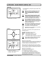
Page 19: ... give the transmitter to anyone who is not fully conversant with the machine its operation and safety directives Repeated high speed setting is only possible after 30 sec of low speed Operating OPERATION RADIO REMOTE CONTROL UNIT WARNING WARNING WARNING WARNING CAUTION 3 Engine speed switch high low L000338C 3 WARNING 2 Speed switch High Low 4 Vibration switch Manual Automatic 6 Vibration switch d...

Page 20: ... unauthorized starting of the ma chine OPERATION RADIO REMOTE CONTROL UNIT The machine will immediately stop when the emergency stop knob on the machine is pressed Make sure that the emergency stops is always in working order The machine stops immediately when you release the joystick Make sure that the joystick is working and that it returns to zero mode on being released The machine stops immedi...

Page 21: ... side 2 Control switch for forward and reverse right side 3 Switch high low speed Vibration can only be used when switch is in low 4 Switch for vibration on off clockwise counterclockwise 5 Emergency stop 6 Throttle control 7 Fuse box 8 Start button 9 Battery disconnector 5 3 4 7 9 8 L000624A L000625B ...

Page 22: ... 6 6 Close the rear service cover CHECKS BEFORE STARTING Observe the safety regulations Ensure that Daily Maintenance has been carried out see schedule Check engine oil level Check hydraulic oil level Check fuel level Check scraper adjustment Check function emergency brake Visually inspect the machine for hydraulic leaks and loose bolts Starting the engine manual controls 1 2 3 OPERATION TEMPORARY...

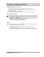
Page 23: ...crete Use vibration only when machine is moving The Vibration Switch functions only when the Speed Switch is set to Low it will not operate in High The switch has 3 positions ON Forward OFF and ON Reverse This allows the operator to select the direction of rotation of the eccentric shaft to improve traction OPERATION TEMPORARY OPERATED Stopping the engine manual controls 1 Turn off vibration Set t...

Page 24: ...24 LP8500 ILP8500EN1 Driving the machine forward Turning the machine to the right Turning the machine to the left Driving the machine reverse OPERATION TEMPORARY OPERATED L000356C ...

Page 25: ...ms 1675 3 693 Lifting L000359C Machine ready for lifting 1 Lifting lug Transportation L000339B Always lash the machine securely for all transportation Use the front and rear towing attachments to lash the machine Clamp down the roller with lashing strap 1 both front and rear decals indicate the fixing points Clamp down force max 40 kN per tie down eye Towing of the machine is forbidden Machine rea...

Page 26: ...heck the Engine Oil Level 28 2 Check Hydraulic Oil Level 28 3 Check Fuel Tank Level 28 4 Check Air Cleaner evacuator valve 28 5 Check Scraper adjustment 28 Check all bolts and nuts for thigtness Every 10 hours Daily Fig 1 10 5 3 7 2 Study the engine instruction manual and follow the maintenance instructions 12 1 9 11 6 8 MAINTENANCE SERVICE POINTS L000363D 1 Engine Oil 2 Tank for Hydraulic Oil 3 F...

Page 27: ...pet clearance See engine manual 7 Replace the Hydraulic Filter 29 8 Replace the Fuel Filter 30 12 Drain Fuel Filter dewateringfilter 30 9 Replace the Air Filter 30 10 Check that the battery terminals are clean and tight 31 Check the engine spacer bolts 31 Item in fig Maintenance see page Comments 2 Change the Hydraulic Oil 32 7 Change Hydraulic Filter 29 Every 1000 Hours MAINTENANCE SERVICE POINTS...

Page 28: ... to upper mark if necessary 6 5 1 4 3 2 7 Check the engine oil level Check hydraulic oil level Check fuel tank level Check air cleaner Check the scraper adjustment 1 Wipe of the oil level gauge 3 and check that the level is in the middle of the glass If necessary fill up 4 If the level is sinking check for leakage 1 Check air inlet opening clean if necessary 2 Check dust extractor valve 6 for free...

Page 29: ...back the cover and check that there is no leakage Pls also read engine instruction book Warning of scalding due to hot oil 1 Only drain off engine oil when the engine is warm 2 Unscrew oil drain plug 1 and drain off oil com pletely 3 Refit the oil drain plug 1 and thigten 4 Using a band wrench loosen the lub oil filter 2 and remove Always replace the lub oil filter 5 Clean the sealing surface 3 th...

Page 30: ...ne cover and dust extractor valve for defor mation aging and cracks replace if necessary 3 Unscrew collar nut 7 4 Pull out filter cartridge 8 carefully 5 The cartridge may not longer be used if there is damage to the filter or in the area of the lipseal 9 6 Pull guide 10 from filter housing 11 7 Clean all parts apart from the filter cartridge Do not spray into the inlet opening to the engine 8 Rep...

Page 31: ...to avoid the accumulation of highly explosive gases Dispose of batteries environmentally 1 Clean the battery poles and clamps and cover them with acid free grease Vaseline 2 Tighten the terminal clamps 3 Check the battery bracket fastening Check that the battery terminals are clean and tight Ensure that the engine spacer bolts are properly tightened Check the engine spacer bolts 1 MAINTENANCE EVER...

Page 32: ...g again with new sealing 4 Change the filter element 5 Fill with hydraulic fluid 6 Check the oil level meter 3 see under the Mainte nance Every 10 hours of operation heading Clean the fuel tank 1 Place a receptacle of at least 17 litres 18 qts under the fuel tank on the left side on the machine Clean the area around and remove the drain plug 1 2 Drain the tank and clean Refit the drain plug with n...

Page 33: ...rapers 5 16 with screw 17 3 Unscrew screws 22 on both sides and remove cover 4 4 Unscrew screw 11 and remove the drum 5 Clean the contact surfaces carefully 6 Mount new drum and fasten with screw 11 Note Torque and locking 7 Assemble cover 4 Note that there is a seal 8 Place the scrapers 5 and 16 Note Torque and locking Change the O rings when assem bling the drum motors Fasten the wheelmotor with...

Page 34: ...Box 504 SE 371 23 Karlskrona Sweden Phone 46 455 30 60 00 Fax 46 455 30 60 30 www dynapac com ...

Reviews: