background image

Preventive maintenance

IPL350TD-1EN2.pdf

2012-06-18

Preventive maintenance

Complete maintenance is necessary for the machine
to function satisfactorily and at the lowest possible
cost.

The Maintenance section includes the periodic
maintenance that must be carried out on the machine.

The recommended maintenance intervals assume that
the machine is used in a normal environment and
working conditions.

Acceptance and delivery inspection

The machine is tested and adjusted before it leaves
the factory.

On arrival, before delivery to the customer, delivery
inspection must be conducted as per the check list in
the warranty document.

Any transport damage must be immediately reported
to the transport company.

Warranty

The warranty is only valid if the stiplulated delivery
inspection and the separate service inspection have
been completed as per the warranty document, and
when the machine has been registered for starting
under the warranty.

The warranty is not valid if damage has been caused
by inadequate service, incorrect use of the machine,
the use of lubricants and hydraulic fluids other than
those specified in the manual, or if any other
adjustments have been made without the requisite
authorisation.

63

Summary of Contents for PL350 TD

Page 1: ...enance Planer Planer PL350 TD PL350 TD Diesel engine Diesel engine Cummins B3 3 Cummins B3 3 Serial number Serial number 10000900x0A006571 10000900x0A006571 Translation of original instructions Translation of original instructions Reservation for changes Reservation for changes Printed in Sweden Printed in Sweden ...

Page 2: ......

Page 3: ...ns 9 Standard lubricants and other recommended oils and fluids 9 Higher ambient temperatures above 40 C 104 F 9 Lower ambient temperature Freeze risk 9 Temperatures 9 High pressure cleaning 10 Fire fighting 10 Battery handling 10 Jump starting 24V 11 Technical specifications 13 Vibrations Operator station 13 Noise level 13 Dimensions side view 14 Dimensions top view 15 Weights and volumes 16 Worki...

Page 4: ... 25 Control panel and controls 25 Functional description of control panel 26 Electrical system 28 Main fuses 28 Fuses machine 29 Relays machine 29 Functional description 30 Front plate 30 Footplate extension option 30 Driver s seat option 31 Conveyor belt option 31 Rear door 32 Safety switch 33 Working lights 34 Vandalism protection 35 Stop valve milling drum freewheel 35 Bits Tool holder 35 Typic...

Page 5: ...eration 43 Positioning 43 Driving the machine 43 Driving on difficult surfaces 44 Drive wheels 44 Swivel chassis leg 45 Direction of steering indicator 45 Pointer 45 Milling Levelling 46 Milling depth indicator adjustment 46 Milling depth indicator Position stop 47 Flow valve 47 Ballast rear Adjusting machine weight 48 Ballast front Adjusting machine weight 48 Milling instructions 49 Milling posit...

Page 6: ... Reserve brake 54 Emergency braking 55 Parking 55 Parking Switching off 55 Master switch 55 Cleaning the machine 56 Long term parking 57 Battery 57 Engine 57 Watering system 57 Hoods tarpaulin 57 Miscellaneous 59 Lifting 59 Lifting the planer 59 Towing Recovery 60 Releasing the brakes 60 Towing the planer 61 Transport 61 Machine prepared for transport 61 Preventive maintenance 63 Acceptance and de...

Page 7: ...y 2000 hours of operation Yearly 70 Maintenance 10h 71 Diesel engine Check oil level Filling 71 Hydraulic reservoir Check fluid level 72 Fuel tank Filling 72 Check the high pressure hydraulic filter 73 Check return filter suction side 73 Water tank filling 74 Sprinkler system nozzles Checking Cleaning 74 Water filter Checking Replacing 75 Clean cooler 75 Check level radiator 76 Brake function Emer...

Page 8: ...k Replace air cleaner s filter element 86 Air cleaner Cleaning 87 Maintenance 500h 89 Fuel filter Replacement 89 Fuel filter Bleeding the filter 90 Hydraulic reservoir cap Check 91 Hydraulic hoses Check 91 Water tank Emptying Cleaning 92 Maintenance 2000h 93 Fuel tank Drainage 93 Hydraulic reservoir Fluid change 94 Return oil filter suction side Replacement 95 Drive wheel Planetary gear oil draini...

Page 9: ... from the machine to provide additional stability when milling on various surfaces Intended use PL 350 TD is mainly intended to be used for roadworks to remove layers of asphalt asphalt concrete and concrete remove superficial irregularities in the form of ruts lateral unevenness and distortions to restore the correct surface profile roughen up and remove markings to carry out preparations in conj...

Page 10: ...nd loose connections are discovered at as early a point in time as possible Inspect the machine every day before starting Inspect the entire machine so that any leakages or other faults are detected Check the ground under the machine Leakages are more easily detected on the ground than on the machine itself THINK ENVIRONMENT Do not release oil fuel and other environmentally hazardous substances in...

Page 11: ...on sharp bends 6 Drive carefully on sharp bends 7 Avoid driving across slopes Drive straight up or straight down the slope 7 Avoid driving across slopes Drive straight up or straight down the slope 8 Make sure that the underlying surface is sufficiently stable 8 Make sure that the underlying surface is sufficiently stable 9 Make sure that there are no obstacles in the direction of travel on the gr...

Page 12: ...c fluid has reached its normal working temperature Braking distances can be longer than normal when the fluid is cold See instructions in the STOP section 18 For your own safety always wear a helmet work shoes with steel toecaps hearing protection breathing protection while milling if necessary reflective clothing high visibility vest work gloves eye protection if necessary 18 For your own safety ...

Page 13: ...hines The operator may allow a person to remain in the danger area but should then observe caution and operate the machine only when the person is visible or has given clear indications of where he or she is The operator may allow a person to remain in the danger area but should then observe caution and operate the machine only when the person is visible or has given clear indications of where he ...

Page 14: ...the center of gravity can cause the machine to tip over on slopes with lower gradients Follow the recommendations for maximum permitted angle in the picture Follow the recommendations for maximum permitted angle in the picture Safety cannot be guaranteed when the max permitted angle of inclination is exceeded Safety cannot be guaranteed when the max permitted angle of inclination is exceeded Where...

Page 15: ...area while the machine is in use The operator must make sure that nobody is in the working area while the machine is in use Risk of body and crush injuries The conveyor has rotating parts Risk of body and crush injuries The conveyor has rotating parts Risk of being retracted Rotating conveyor Risk of being retracted Rotating conveyor The overall length of the machine is changed when the conveyor i...

Page 16: ...Safety Optional IPL350TD 1EN2 pdf 2012 06 18 8 ...

Page 17: ...4 F For operation of the machine at higher ambient temperatures however maximum 50 C 122 F the following recommendations apply The diesel engine can be run at this temperature using normal oil However the following fluids must be used for other components Hydraulic system mineral oil Shell Tellus T100 or similar Lower ambient temperature Freeze risk Make sure that the watering system is empty drai...

Page 18: ...ould cause malfunctions such as the blocking of filters Never aim the water jet directly at the fuel tank cap This is particularly important when using a high pressure cleaner Never aim the water jet directly at the fuel tank cap This is particularly important when using a high pressure cleaner Fire fighting If the machine catches fire use an ABC class powder fire extinguisher A BE class carbon di...

Page 19: ...ng has the same voltage as the dead battery 24V 12V 12V Fig Jump starting 1 2 3 4 Turn the ignition and all power consuming equipment off Switch off the engine on the machine which is providing jump start power Jump leads must have 24V First connect the jump start battery s positive terminal 1 to the flat battery s positive terminal 2 Then connect the jump start battery s negative terminal 3 to fo...

Page 20: ...Special instructions IPL350TD 1EN2 pdf 2012 06 18 12 ...

Page 21: ...lue of 0 5 m s specified in directive 2002 44 EC The limit is 1 15 m s Measured hand arm vibrations also were below the action level of 2 5 m s specified in the samedirective Limit is 5 m s Measured hand arm vibrations also were below the action level of 2 5 m s specified in the samedirective Limit is 5 m s Noise level The noise levels are measured in accordance with the operational cycle describe...

Page 22: ... inch Dimensions mm degrees inch A 3880 153 A 3880 153 B 2855 112 B 2855 112 C 2480 98 C 2480 98 D 1555 61 D 1555 61 E 300 12 E 300 12 F 375 14 8 F 375 14 8 G 625 24 6 G 625 24 6 H 1025 40 4 H 1025 40 4 I1 685 27 I1 685 27 I2 750 29 6 I2 750 29 6 J 305 12 J 305 12 K 2000 79 K 2000 79 V 26 V 26 14 ...

Page 23: ...18 Dimensions top view Dimensions mm degrees inch Dimensions mm degrees inch L 410 16 L 410 16 M 740 29 M 740 29 N 290 11 4 N 290 11 4 O 1010 40 O 1010 40 P 1030 40 5 P 1030 40 5 S 1310 51 6 S 1310 51 6 T1 20 T1 20 T2 10 T2 10 U1 75 U1 75 U2 75 U2 75 15 ...

Page 24: ...15 kg 255 lbs Fluid volumes Fluid volumes PL350TD PL350TD Fuel tank 125 l 33 gal Fuel tank 125 l 33 gal Engine oil 7 5 l 8 qts Engine oil 7 5 l 8 qts Hydraulic reservoir 110 l 116 qts Hydraulic reservoir 110 l 116 qts Water tank 400 l 123 gal Water tank 400 l 123 gal Planetary gear drive wheel 0 75 l 0 8 qts Planetary gear drive wheel 0 75 l 0 8 qts Coolant engine 4 5 l 4 8 qts Coolant engine 4 5 ...

Page 25: ...d 11 6 l h kg Fuel consumption 2 3 load 8 0 l h kg Fuel consumption 2 3 load 8 0 l h kg Electrical system Electrical system Voltage 24 V Voltage 24 V High capacity batteries 2 x 12 V 74 Ah High capacity batteries 2 x 12 V 74 Ah Alternator 24 V 35 A Alternator 24 V 35 A Fuses see section on fuses Fuses see section on fuses Hydraulic system Hydraulic system Pressure generation Hydraulic pumps flange...

Page 26: ...30 370 470 520 560 620 M22 446 497 626 699 752 839 M22 446 497 626 699 752 839 M24 570 640 800 900 960 1080 M24 570 640 800 900 960 1080 M30 1130 1260 1580 1770 1900 2100 M30 1130 1260 1580 1770 1900 2100 STRENGTH CLASS Metric coarse screw thread bright galvanized fzb Metric coarse thread zinc treated Dacromet GEOMET STRENGTH CLASS M thread 10 9 Oiled 10 9 Dry 12 9 Oiled 12 9 Dry M thread 10 9 Oil...

Page 27: ...00123 V 0 A 123456 100 00123 V 0 A 123456 A B C D E F A B C D E F A Manufacturer B Family Model C Check letter D No coding E Production unit F Serial number 1 Fig PIN Front frame Product identification number on the frame The machine PIN product identification number 1 is punched on the front right hand side of the frame 19 ...

Page 28: ...achine plate 1 is fixed to the right hand side of the frame by the chassis leg The plate gives the name and address of the manufacturer type of machine PIN serial number operating weight engine power axle weight front rear and year of manufacture Please state the machine s PIN when ordering spares 20 ...

Page 29: ...ating milling drum D956052007 10 Lifting plate 4700904870 3 Warning Rotating milling drum D956052007 10 Lifting plate 4700904870 4 Coolant 4700388449 11 Ear protection 4700388449 4 Coolant 4700388449 11 Ear protection 4700388449 5 Lifting point 4700357587 12 Warning Instruction manual 4700903459 5 Lifting point 4700357587 12 Warning Instruction manual 4700903459 6 Warning Hot surfaces 4700903424 1...

Page 30: ...late 4700904870 17 Warning Brake disengagement 4700904895 22 Master switch 4700904835 17 Warning Brake disengagement 4700904895 22 Master switch 4700904835 18 Warning Rotating engine components 4700903423 23 Manual compartment 4700903425 18 Warning Rotating engine components 4700903423 23 Manual compartment 4700903425 19 Warning Hot surfaces 4700903424 19 Warning Hot surfaces 4700903424 Fig Locati...

Page 31: ...zone 4700904895 Warning Brake disengagement Study the towing chapter before disengaging the brakes Danger of being crushed 4700903424 Warning Hot surfaces in the engine compartment Keep your hands at a safe distance from the danger zone 4700903459 Warning Instruction manual The operator must read the safety operation and maintenance instructions before operating the machine 4700791642 Warning Star...

Page 32: ... zone Info decals Handbook compartment Noise power level Master switch Handbook compartment Noise power level Master switch Diesel fuel Water Hydraulic fluid level Diesel fuel Water Hydraulic fluid level Fixing point Lifting plate Lift point Fixing point Lifting plate Lift point Ear protection Coolant Ear protection Coolant 24 ...

Page 33: ...ne 4 Speed setting 13 Position setting Conveyor belt Hydraulic hammer 22 Indicator Preheating of diesel engine 5 Forward Reverse lever 14 Position selector scraper 23 Warning lamp battery charging 5 Forward Reverse lever 14 Position selector scraper 23 Warning lamp battery charging 6 Horn 15 Floating position scraper 24 Start inhibitor 6 Horn 15 Floating position scraper 24 Start inhibitor 7 Ignit...

Page 34: ...he horn 7 Ignition key Position P Parking lights on Position 0 The electric circuit is broken Secondary brake on Position I All instruments and electric controls are supplied with power Position II Start function 7 Ignition key Position P Parking lights on Position 0 The electric circuit is broken Secondary brake on Position I All instruments and electric controls are supplied with power Position ...

Page 35: ...ergency stop Switches off diesel engine drive units and steering 17 Outlet Extra 24 V outlet 17 Outlet Extra 24 V outlet 18 Temperature gauge cooling system Displays the temperature of the coolant 18 Temperature gauge cooling system Displays the temperature of the coolant 19 Working hours counter Displays the number of working hours 19 Working hours counter Displays the number of working hours 20 ...

Page 36: ...ine has The fuse box and relays are placed behind the left hand engine cover The machine is equipped with a 24 V electrical system and an AC alternator Main fuses Fig Engine compartment positioning of main fuses There are four main fuses placed behind the left hand cover on the engine compartment F1 1 Main fuse 50A F1 1 Main fuse 50A F1 2 Main fuse alternator 50A F1 2 Main fuse alternator 50A 28 ...

Page 37: ...nit computer 10A 4 Control unit computer 10A 5 Milling drum scraper water system conveyor belt option 10A 5 Milling drum scraper water system conveyor belt option 10A 7 Working lights 25A 7 Working lights 25A 8 Rotating hazard light 5A 8 Rotating hazard light 5A 9 Horn buzzer 10A 9 Horn buzzer 10A 10 Levelling system 10A 10 Levelling system 10A 11 Plugs 24V 10A 11 Plugs 24V 10A Relays machine Fig ...

Page 38: ...dle located in front of the steering wheel 2 The front plate must be folded down during milling The front plate must be folded down during milling Footplate extension option Fig 1 Extra footplate 2 Support handle 1 2 An additional extension of the footplate 1 can be hooked onto the existing footplate to provide more space Under the plate are 2 adjustment screws which must be locked into position a...

Page 39: ...he reverse order Conveyor belt option Fig Conveyor belt 1 Crank handle 2 Locking device 1 2 The conveyor belt can be adjusted vertically and laterally Vertical output is adjusted using the crank handle 1 Sideways movement is achieved by undoing the locking device 2 Turn the entire conveyor belt by hand to the desired position Securely lock the locking device Adjustments may only be performed when ...

Page 40: ...ned by opening the locking pin 2 and pulling the catch 3 to the side Close the door properly before commencing milling work If the door is open and the safety switch 4 is deactivated the transmission for the milling drum will be switched off If the door is open and the safety switch 4 is deactivated the transmission for the milling drum will be switched off Fig Open rear door 4 Safety switch 4 32 ...

Page 41: ...will stop after a short distance if the pressure from the driver is removed from the plate The safety switch by the rear door interrupts operation of the milling drum when the door is open Fig 2 Safety switch rear door 2 If one of the safety switches is deactivated the control lever must be moved to neutral before the machine can be driven again If one of the safety switches is deactivated the con...

Page 42: ...for working lights NB The sockets are 24 volt sockets Place the working lights in position and secure with a wing nut 1 2 Fig Vertical adjustment rotating beacon 2 Screw The rotating beacon located on the left hand side of the control panel can be adjusted vertically by undoing the screw 2 setting the correct height and then tightening the screw again 34 ...

Page 43: ...ng drum 1 Stop valve freewheel The stop valve 1 is used during maintenance work or when replacing milling teeth To disengage lock the milling drum freewheel Vertical position Freewheel locked Milling position Horizontal position Freewheel free Possible to turn milling drum Bits Tool holder Fig Quick coupling system 1 Bits 2 Tool holder 1 2 System C10HD The double action quick coupling system C10HD...

Page 44: ...Typical wear marks on bits The condition of bits wear rings and tooth holders should be checked several times a day Replace immediately if there are visible signs of wear or damage New unused milling bit New unused milling bit Worn milling bit replace immediately Worn milling bit replace immediately Eroded milling bit replace immediately Eroded milling bit replace immediately One side worn milling...

Page 45: ... the hammer punch in the hole on the back of the tool holder and knock out the bit with a hammer Clean the holes and contact surfaces before fitting new teeth Fig Fitting bits Fitting new bit Knock in the new bits in the tool holders with a hammer Use copper brass or plastic hammers Steel hammers damage the tip of the milling tooth Use copper brass or plastic hammers Steel hammers damage the tip o...

Page 46: ...ve tool holder The tool holders are only replaced when they are defective Remove the defective holder Carefully clean the contact surface Place the new holder with inserted bits on the drum and weld on Make sure the tip of the bit is on the same position as before Fig Position new tooth holder 38 ...

Page 47: ...steps off the standing plate operation is interrupted and the machine stops after a short distance If the safety switch has been deactivated the control lever must be moved to neutral before the machine can be operated If the safety switch has been deactivated the control lever must be moved to neutral before the machine can be operated Stand on the plate at all times when operating the machine St...

Page 48: ... Driver seat Adjustment option Adjust the operator s seat so that the position is comfortable and so that the controls are within easy reach The seat can be adjusted as follows Length adjustment 1 Height adjustment 2 Weight adjustment 3 Always make sure that the seat is secure before beginning operation Always make sure that the seat is secure before beginning operation Fig Vandalism protection Un...

Page 49: ...amps for the engine 2 go on Check that the rotating beacon 3 and other lights 4 are working Master switch Switching on Fig Battery disconnector Remember to carry out daily maintenance Refer to the maintenance instructions The battery isolator is located under the left hand engine cover Turn the key to the On position The planer is now supplied with power 41 ...

Page 50: ...max 30 seconds If the engine will not start wait a minute before trying again Do not run the starter motor for too long max 30 seconds If the engine will not start wait a minute before trying again Allow the engine to idle for a few minutes with no load to warm up longer if the air temperature is below 10 C 50 F The milling drum should be engaged Ensure that there is good ventilation air extractio...

Page 51: ...ration Under no circumstances is the machine to be operated from the ground The operator must be standing on the platform or sitting in the driver s seat at all times when the machine is in operation Raise the machine 1 so that the milling drum clears the ground about 10 cm Check that the steering is working by turning the steering wheel once to the right and once to the left while the planer is s...

Page 52: ...er by changing the engine speed The speed should always be controlled using the forward reverse lever and never by changing the engine speed Check while driving that all the gauges 5 show normal readings Stop the planer and engine immediately in the event of abnormal values Check and correct any faults see also the section on maintenance and the engine manual Driving on difficult surfaces Drive wh...

Page 53: ...t the pin and swing the chassis leg in towards the machine 2 Secure the chassis leg and insert the pin again 1 Fig 1 Direction of travel indication Direction of steering indicator The direction of steering indicator is located on the top of the machine The indicator is connected to the front wheel s steering and shows the direction position of the front wheel Pointer 2 1 Fig Direction indicator 1 ...

Page 54: ...or the position of both sides Chassis leg extended Chassis leg withdrawn Let the machine be at level ground Lower the spinning milling drum until both sides lightly scratches the surface Adjust the indicator by releasing the retaining screw 1 and set the pointer 2 to zero Tighten the retaining screw The stroke length on each chassis leg is shown in centimeters and optionally in inches The stroke l...

Page 55: ...rn the shaft to the desired position using the crank 1 Lock the shaft in position with the locking lever 2 Before the milling depth can be increased the position stop must first be undone and the shaft cranked up Before the milling depth can be increased the position stop must first be undone and the shaft cranked up Flow valve 1 Fig Flow valve 1 Flow valve Adjusting the speed to raise lower the t...

Page 56: ...ve or add weights in order to reduce the machine weight The weights which are located inside the rear door on the machine are stacked on top of each other and held in place by a rail 2 and screw 3 1 Fig Ballast 1 Front plate Ballast front Adjusting machine weight The machine weight should always be as high as possibly At some applications e g milling inside buildings with a celler underneath it is...

Page 57: ... speed Lower the drum until the bits scrape against the ground along the full width of the drum Reset the scale for the milling depth Resetting must be performed on right rear foldable leg both when folded in and folded out Always reset on a horizontal not inclined surface Resetting must be performed on right rear foldable leg both when folded in and folded out Always reset on a horizontal not inc...

Page 58: ...e milling drum where the ground has still not been milled Depth setting Same milling depth on right and left side Milling at edge of roadway or at shoulders Fig Milling at edge of roadway or at shoulders Depth setting left required milling depth right required milling depth shoulder height alternatively with planer horisontal The planer must always be maintained in horisontal position when planer ...

Page 59: ...e Direct milling to curb edge is possible Disadvantages In some circumstances it is not possible to achieve the required milling depth Milling at curb edge with folded in chassis leg Fig Milling at curb edge with withdrawn chassis leg Advantages Max milling depth achieved Direct milling to curb edge is possible Disadvantages Less milling precision Machine is very sensitive to irregularities 51 ...

Page 60: ...hat the lamp means and rectify the fault Do not start milling if a warning lamp on the control panel comes on Check what the lamp means and rectify the fault Lower the machine manually as far as possible without the milling drum coming into contact with the ground with the two switches chassis leg right and left 1 2 Activate the following functions on the control panel Put the gear position switch...

Page 61: ...ions for the conveyor belt will engage as soon as the milling drum is in operation and the control lever is activated The sprinkler system and automatic functions for the conveyor belt will engage as soon as the milling drum is in operation and the control lever is activated 5 Fig Control panel 1 Control lever 2 Leveling 3 Chassis leg left 4 Chassis leg right 5 Milling drum drive 6 Water pump 7 Ge...

Page 62: ...luid is also cold and that braking distances can be longer than normal until the machine reaches the working temperature Parking brake Putting the control lever 1 in neutral stops the machine and activates the parking brake Multi disc in front motor Parking brake is activated even when engine is turned off 1 Fig Control panel 1 Ignition lock Reserve brake Turn the ignition key 1 to position 0 The ...

Page 63: ...e Parking Fig Control panel 1 Hours of operation 2 Ignition lock 1 2 Parking Switching off Always park the machine on the most level surface Never park the machine with running engine Never park the machine with running engine Before leaving the machine Lower the machine until the milling drum almost touches the ground Read off status for working hours 1 and check if any maintenance is need before...

Page 64: ...l milling material Lubricate bearings and support leg after cleaning Check that side shields front shield and scraper are properly secured and slide in their tracks without jamming Clean the tracks daily Do not spray water directly onto bearings and electronic components Do not spray water directly onto bearings and electronic components 56 ...

Page 65: ...d trickle charge the battery once a month The battery is otherwise maintenance free Engine See the manufacturer s instructions in the engine manual Watering system Empty the water tank and all hoses of water Empty the filter housing and the water pump Undo all sprinkler nozzles See maintenance sections for Watering system draining Hoods tarpaulin Lower the instrument cover over the instrument pane...

Page 66: ...Long term parking IPL350TD 1EN2 pdf 2012 06 18 58 ...

Page 67: ...e is noted on the machine plate located by the swivel chassis leg The gross weight of the machine is noted on the machine plate located by the swivel chassis leg Lifting equipment such as chains steel wires straps and lifting hooks must be dimensioned in accordance with the relevant safety regulations for the lifting equipment Lifting equipment such as chains steel wires straps and lifting hooks m...

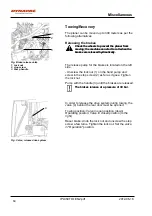
Page 68: ...y The release pump for the brakes is located on the left side Unscrew the lock nut 1 on the hand pump and screw in the stop screw 2 as far as it goes Tighten the lock nut Pump with the handle 3 until the brakes are released The brakes release at a pressure of 30 bar The brakes release at a pressure of 30 bar Fig Valve release drive system 4 In order to release the drive system during towing the va...

Page 69: ...ng in only 1 of the eyes is prohibited The total retrieval load may amount to max 5 tonnes Transport Machine prepared for transport Fig 1 Machine loaded on low loader The right chassis leg must be folded out and locked before transport and lifting follow the instructions under respective headings The right chassis leg must be folded out and locked before transport and lifting follow the instructio...

Page 70: ...ine according to the cargo securing rules that are valid for the country where the transport takes place Make sure that the lashing equipment e g chains blocks and attachments in the transport vehicle are approved and have the requisite breaking strain for the mode of transport The lashing must be held tensioned during the entire transport Make sure that the lashing equipment e g chains blocks and...

Page 71: ... arrival before delivery to the customer delivery inspection must be conducted as per the check list in the warranty document Any transport damage must be immediately reported to the transport company Warranty The warranty is only valid if the stiplulated delivery inspection and the separate service inspection have been completed as per the warranty document and when the machine has been registere...

Page 72: ...Preventive maintenance IPL350TD 1EN2 pdf 2012 06 18 64 ...

Page 73: ... Optimol Optigear or equivalent Dynapac Gear oil 300 P N 4812030756 5 liters P N 4812030103 20 liter P N 4812031573 209 liters TRANSMISSION OIL Gearbox oil 220 Planetary gear Air temperature 15 C 40 C 5 F 104 F Optimol Optigear or equivalent Dynapac Gear oil 300 P N 4812030756 5 liters P N 4812030103 20 liter P N 4812031573 209 liters TRANSMISSION OIL Gearbox oil 90 angular planetary gearing Only ...

Page 74: ...volumes Fluid volumes PL350TD PL350TD Fuel tank 125 l 33 gal Fuel tank 125 l 33 gal Engine oil 7 5 l 8 qts Engine oil 7 5 l 8 qts Hydraulic reservoir 110 l 116 qts Hydraulic reservoir 110 l 116 qts Water tank 400 l 123 gal Water tank 400 l 123 gal Planetary gear drive wheel 0 75 l 0 8 qts Planetary gear drive wheel 0 75 l 0 8 qts Coolant engine 4 5 l 4 8 qts Coolant engine 4 5 l 4 8 qts 66 ...

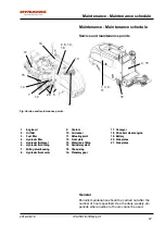
Page 75: ...Refueling point 19 Battery 4 Hydraulic filter 12 Front plate 20 Side plates 4 Hydraulic filter 12 Front plate 20 Side plates 5 Hydraulic fluid level 13 Water tank filling 21 Side plates 5 Hydraulic fluid level 13 Water tank filling 21 Side plates 6 Hydraulic fluid filling 14 Sprinkler system 6 Hydraulic fluid filling 14 Sprinkler system 7 Milling drum housing 15 Chassis leg 7 Milling drum housing ...

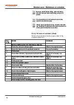
Page 76: ... Check the fluid level in the hydraulic reservoir Top up if necessary 11 Fill fuel tank 11 Fill fuel tank 4 Check filter indicator high pressure hydraulic filter Replace if necessary see 2000 h 4 Check filter indicator high pressure hydraulic filter Replace if necessary see 2000 h 4 Check return oil filter suction side indication control panel Replace if necessary see 2000 h 4 Check return oil fil...

Page 77: ...operation Refer to the contents to find the page number of the sections referred to Pos in fig Action Comment Pos in fig Action Comment 16 Change oil in planetary gear drive wheel See section Drive wheel Planetary gear oil draining 2000 hours 16 Change oil in planetary gear drive wheel See section Drive wheel Planetary gear oil draining 2000 hours 16 Adjust visible screws nuts planetary gear drive...

Page 78: ...ts to find the page number of the sections referred to Pos in fig Action Comment Pos in fig Action Comment 3 Check engine valve clearances Refer to the engine manual 3 Check engine valve clearances Refer to the engine manual 9 Replace coolant 9 Replace coolant 16 Check visible screws nuts planetary gear drive wheel Tighten if necessary 16 Check visible screws nuts planetary gear drive wheel Tighte...

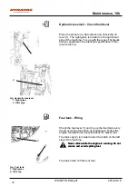
Page 79: ...l engine Check oil level Filling Fig Engine compartment left hand machine side 1 Dipstick 2 Filling 1 2 Take care not to touch any hot parts of the engine or the radiator when removing the dipstick Risk for burns Take care not to touch any hot parts of the engine or the radiator when removing the dipstick Risk for burns The dipstick is placed behind the left cover in the engine compartment Pull up...

Page 80: ...icant specification if the level is too low Fuel tank Filling Fig Fuel tank 1 Sight glass 2 Tank cap 1 2 Check the fuel level 1 and top up the fuel tank every day to avoid the formation of condensate Follow the engine manufacturer s specifications for diesel fuel The tank cap 2 is located under the hatch on the left side of the machine Never refuel while the engine is running Do not smoke and avoi...

Page 81: ...d replaced when necessary After repairs to the hydraulic systemet all filters must be checked after 10 working hours and replaced when necessary Check return filter suction side Fig Control panel 1 Alarm return filter 1 The filter unit must be replaced when an alarm 1 is shown on the control panel or at intervals of 2000 h After repairs to the hydraulic systemet all filters must be checked after 1...

Page 82: ...es Checking Cleaning Fig Sprinkler nozzle 1 Nozzle The nozzles are located on the milling drum housing Start the sprinkler system and make sure that no nozzles 1 are clogged Clean any blocked nozzles if necessary Release the pipe together with the nozzles from their attachments Clean the nozzles with a wire brush Remove the nozzle if necessary for replacement or more carefully cleaning When fittin...

Page 83: ...orrectly positioned Always dispose of old filters Never reuse Always dispose of old filters Never reuse Recycle old filters for waste disposal Recycle old filters for waste disposal Clean cooler Fig Cooler Make sure that the air flow through the cooler is unobstructed Dirty coolers are blown clean with compressed air or washed clean using a high pressure water cleaner Take care when using a high p...

Page 84: ...ontrol panel 1 Emergency stop 2 Forward Reverse lever 1 2 Checking the emergency stop Drive the planer slowly forward Hold the steering wheel firmly and brace yourself for a sudden stop Push in the emergency stop 1 The planer should come to a sudden stop and the engine should switch off After checking the emergency stop set the forward reverse lever 2 in neutral Pull up the emergency stop 1 Start ...

Page 85: ...ill stop after a short distance when the pressure from the driver disappears from the plate The safety switch by the rear door will interrupt the operation of the milling drum when the door is open Fig 2 Safety switch rear door 2 If one of the safety switches is deactivated the control lever must be moved to neutral before the machine can be driven forward reversed If one of the safety switches is...

Page 86: ...aintenance 10h IPL350TD 1EN2 pdf 2012 06 18 Diesel engine Checking the drive belt Fig Drive belt Visually check the drive belt every day for damage For maintenance of the drive belt see engine manual 78 ...

Page 87: ...itched off during all checks and adjustments of the planer unless otherwise specified Air cleaner emptying Fig Air cleaner 1 Dust trap 1 Empty the air cleaner s dust pouch 1 every 50 h by pressing the rubber bellows with your fingers Check also that the air hoses are in good condition Clean the air cleaner when operated in extremely dusty environments Fig Front wheel Planetary gear position for re...

Page 88: ...ling housing front and rear 1 Rubber seal 2 Retaining screws 1 2 1 2 The 2 rubber seals 1 are located at the front and rear of the milling housing Check the seals and replace if damaged Undo the retaining screws 2 and remove damaged seal Fit a new seal and tighten the retaining screws 80 ...

Page 89: ... lubricant specification 1 Fig Side plates 1 Side plate right side 2 Side plate left side 3 Slide tracks 3 2 Side plates Check The side plates are located on either side of the milling drum 1 2 Check that the side plates slide in their tracks 3 without catching Clean the tracks daily of milled material Check that the side plates are properly secured and tighten the retaining screws if necessary To...

Page 90: ...1 Retaining screw 2 Side plate 2 Side plates Replacement To replace side plates Undo the 2 retaining screws 1 and remove the side plate 2 Align a new side plate and tighten the retaining screws To access the left hand side plate open the rear door on the machine 82 ...

Page 91: ... the cover plate 1 Fig Battery compartment 1 Cover plate 2 Screws Make sure there are no naked flames in the vicinity when checking the fluid level Explosive gas is produced in the battery Make sure there are no naked flames in the vicinity when checking the fluid level Explosive gas is produced in the battery Wear safety goggles The battery contains acid which is corrosive In the event of contact...

Page 92: ...cked every 250 hours of operation When the slide rail is worn down to the screw head it must be replaced Right hand side Undo 2 retaining screws guide rail 2 Replace the guide rail and install a new one with the retaining screws Fig 2 Slide rails chassis leg left hand side 1 Left hand side Open the rear door on the machine to access the guide rails by the left hand chassis leg The slide rails 2 ar...

Page 93: ...engine warm before draining the oil 1 Fig 1 Drain cock Switch off the engine before draining Switch off the engine before draining Place a suitable container under the drain plug Collect up the oil and hand in to waste disposal station Place a suitable container under the drain plug Collect up the oil and hand in to waste disposal station Danger of being burned when draining hot oil Protect your h...

Page 94: ...l on the new filter Fill the filter with oil and fit in place Tighten by hand Check the seal and oil pressure indicator Top up with new engine oil see section Diesel engine Check oil level See the lubricant specification to obtain the correct oil grade Check the dipstick 3 to ensure that the oil level is correct Refer to the engine manual for details Check Replace air cleaner s filter element Rele...

Page 95: ...inside of the cover 2 and the filter housing 5 See the previous illustration Wipe clean on both sides of the outlet pipe Outer edge of outlet pipe Inner edge of outlet pipe Wipe also both surfaces for the outlet pipe see adjacent figure Check that the hose clamps between the filter housing and the suction hose are tight and that the hoses are intact Inspect the entire hose system all the way to th...

Page 96: ...Maintenance 250h IPL350TD 1EN2 pdf 2012 06 18 88 ...

Page 97: ...ine must be switched off during all checks and adjustments of the planer unless otherwise specified Place the planer on a level surface The engine must be switched off during all checks and adjustments of the planer unless otherwise specified Fuel filter Replacement Fig Fuel filter The fuel filter is located behind the right hand engine compartment cover and must be replaced every 500 h Release th...

Page 98: ...ush button pump Open the bleeder screw 1 bleeding takes place during pumping filling the filter Use the mechanical hand pump located on the fuel filter pump with the push button 2 until resistance is noticed during pumping at which point the filter is filled with fuel Tighten the bleeder screw to the correct torque 90 ...

Page 99: ... with compressed air until free passage is assured or replace the cap with a new one Wear protective goggles when working with compressed air Wear protective goggles when working with compressed air Wear protective gloves when working with diesel Wear protective gloves when working with diesel Hydraulic hoses Check Fig Hydraulic hoses Check the condition of the hydraulic hoses and immediately repl...

Page 100: ...run out Fig Water tank 1 Tap water 1 Clean the tank with water and a suitable detergent Close the tap afterwards Fill up with new water see chapter Water tank Filling Remember that there is a risk of freezing during the winter Empty the tank lines and pump Remember that there is a risk of freezing during the winter Empty the tank lines and pump 92 ...

Page 101: ...ss otherwise specified Fuel tank Drainage Fig Fuel tank 1 Drain plug 1 Water and sediment in the fuel tank are removed via the drainage plug in the bottom of the fuel tank Be very careful during draining Do not drop the plug or else all the fuel will flow out Be very careful during draining Do not drop the plug or else all the fuel will flow out The draining should be done when the planer has been...

Page 102: ...the machine on the right hand side by the chassis leg Place a container under the plug Release the oil plug and allow all the oil to run out Refit the drain plug with a new seal Hand in the drained oil to a waste disposal station Hand in the drained oil to a waste disposal station Top up with new hydraulic fluid see section Hydraulic reservoir Check fluid level See the lubricant specification to o...

Page 103: ...rument panel 3 lights up red Fig Engine compartment left 1 Filter housing cover 1 Fig Filter unit 2 Handle 2 Undo the filter housing cover 1 Lift out the complete filter unit from the housing and remove the handle 2 from the used filter unit Remove the filter and hand in to waste disposal station This is a disposable filter and cannot be cleaned Remove the filter and hand in to waste disposal stat...

Page 104: ...ilter holder 2 Indicator 2 1 High pressure hydraulic filter Replacement The filter units must always be replaced in pairs The filter units must always be replaced in pairs When the indicator 2 indicates red the filter must be replaced Release the filter holder with an Allen key Unscrew by hand Remove the filter 1 and hand in to a waste disposal station This is a disposable filter and cannot be cle...

Page 105: ...hassis leg to its forward position Raise the machine Ensure that the machine cannot drop Ensure that the machine cannot drop Check that the milling drum is not in contact with the surface Remove the side plate 1 Remove the entire cover 2 Undo the milling drum s retaining screws 3 and pull out the drum Refit in the reverse order Check that the retaining screws are clean and tighten to the correct t...

Page 106: ...Dynapac Compaction Equipment AB Box 504 SE 371 23 Karlskrona Sweden ...

Page 107: ...Dynapac Compaction Equipment AB Box 504 SE 371 23 Karlskrona Sweden ...

Reviews: