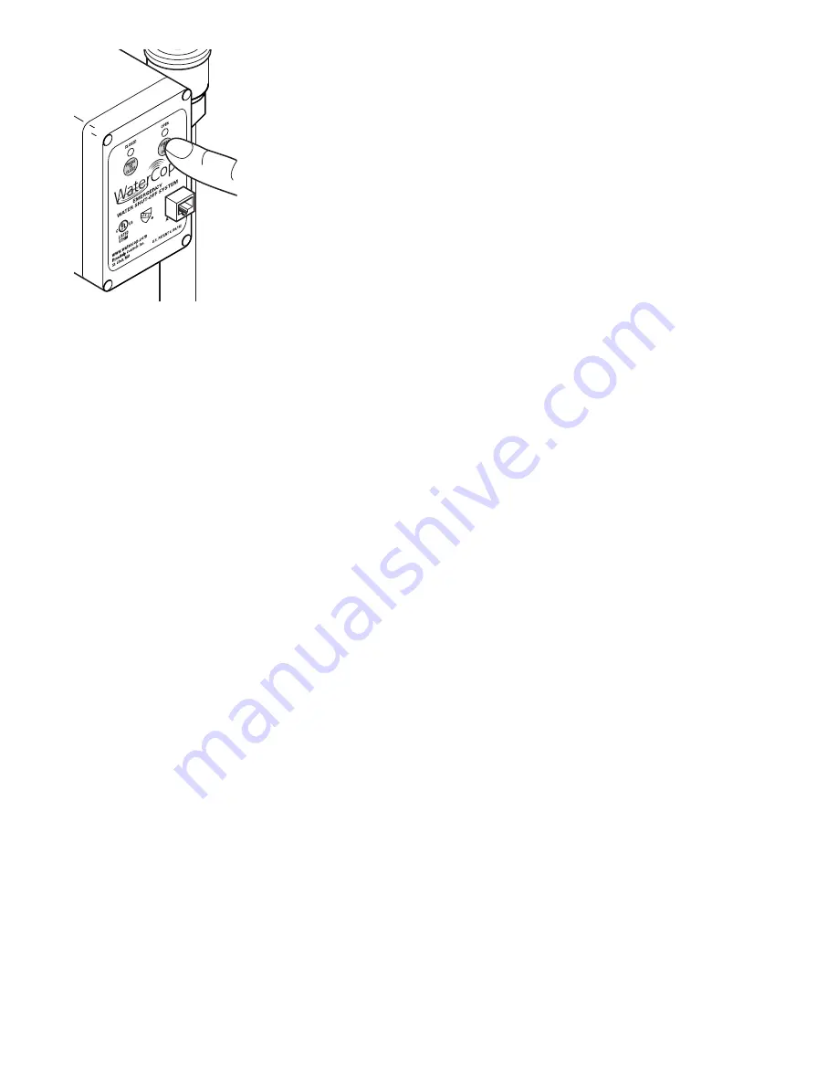
to check all areas where
you have placed a sensor
to determine what plumb-
ing product caused the
system to activate. The
valve will remain closed
until the unit is manually
reset on the WaterCop
®
panel. After the plumbing
problem is fixed, reset the
WaterCop
®
by pressing
"open valve" (green circle)
on the face of the
WaterCop
®
. Valve will
open and green indicator
will be lit. See illustration to
the lower left.
Note: If major repairs are needed to correct the
plumbing system, it is recommended that the manual
shut-off valve upstream of the WaterCop
®
also be
closed during the repairs. Close the main water shut-
off valve and unplug the WaterCop
®
before doing
repairs on the plumbing system.
Note: In case of a power failure, the WaterCop
®
cannot operate. If the power is out, you will need to use
the manual shut-off valve to turn the water off in case
of an emergency. When power is restored, the
WaterCop
®
will remain in its last known position indi-
cated by the red or green lights on the face of the unit.
WaterCop
®
Specifications
Max. working pressure ...125 PSIG
Ambient temperature .....35° to 105° F
Enclosure .......................Polycarbonate
Voltage ...........................115, 1 Phase, 60 Hz
Current ...........................2.5 Amps
Power Input:
Standby ..........................1.375 W
Holding (2.5 sec) ............75 W
Power Cord ....................8 ft. Heavy-Duty Grounded
Valve ..............................Full-Port, Brass, NPT
Valve Seals ....................RTFE
Flow Data
Valve Size Cv = Gpm flow @ 1 PSI pressure drop
1/2" NPT
19
3/4" NPT
34
1" NPT
52
For cold water applications.
FCC Information
This equipment has been tested and found to comply
within limits of a class B digital device, pursuant to part
15 of the FCC Rules. These limits are designed to
provide reasonable protection against harmful
interference in a residential installation. This
equipment generates, uses, and can radiate radio
frequency energy and if not installed and used in
accordance with the instructions, may cause harmful
interference to radio communications. However, there
is no guarantee that interference will not occur in a
particular installation.
The flood sensors only transmit a radio signal during
testing and when contact is made between the probes
as when water is detected. This signal is of a 2-second
duration and is repeated approximately every 6
seconds while activated. This 2 second signal should
be the only time potential interference could be
detected. If you suspect the unit is interfering with your
radio and/or television reception on a prolonged basis,
remove batteries from all transmitters to determine if
this unit is causing the interference. If so, please
consult your dealer.
LIMITED WARRANTY
DynaQuip Controls Corporation warrants the electrical
components of the WaterCop
®
system to be free from
defects in material and workmanship under normal use
and if properly installed for a period of three years from
the date of purchase. If found to be defective as men-
tioned above, it will be replaced or repaired if returned
prepaid along with proof of date of purchase. This shall
constitute the sole remedy of the purchaser and the
sole liability of DynaQuip Controls Corporation. To the
extent permitted by law, the foregoing is exclusive and
in lieu of all other warranties or representations
whether expressed or implied, including any implied
warranty of merchantability or fitness. In no event shall
DynaQuip Controls Corporation be liable for special or
consequential damages.
The WaterCop brass ball valve has a lifetime warran-
tee.
Additional Components available for your
WaterCop
®
Systems:
Single and Dual probe WaterCop
®
Flood Sensors
• WH100 (single probe) and WH200 (dual probe)
• Battery or AC (optional) powered
• Transmits wireless signal to valve when moisture is
detected.
• Unlimited number can be used, placed anywhere
• 6 foot sensor cord, white
Low Temperature Sensor
• FH100
• Monitor temperature of pipes prone to freezing
• Sends wireless signal to turn off water if low temperature
detected
• 5 foot cord with clip to attach to pipe
Water Control Wall Switch
• RS100
• Proactively turn water on or off from convenient location
• Lighted display to valve position (on or off)
• Requires Category 5 cabling connection to valve (see
below)
AC Power Adaptor
• For WH100, WH200, and FH100 sensors.
• Eliminates the need for AA batteries
WaterCop / Wall Switch Interconnect Cable
• CBL50 (50 feet) and CBL100 (100 feet)
• Required to connect WaterCop valve with Water Control
Wall Switch
• RJ45 molded connections for easy installation and
durability
3
Summary of Contents for WaterCop
Page 4: ...4...


