background image

24

Dynaset Oy  |  Menotie 3, FI-33470 Ylöjärvi, Finland  |  tel: +358 3 3488 200  |  info@dynaset.com  |  www.dynaset.com

 HYDRAULIC SCREW COMPRESSORS

OPERATING PRINCIPLES

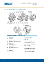
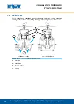
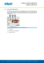
3.8.  MINIMUM PRESSURE VALVE

1

2

3

4

5

6

7

8

A

B

C

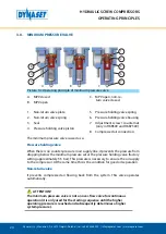
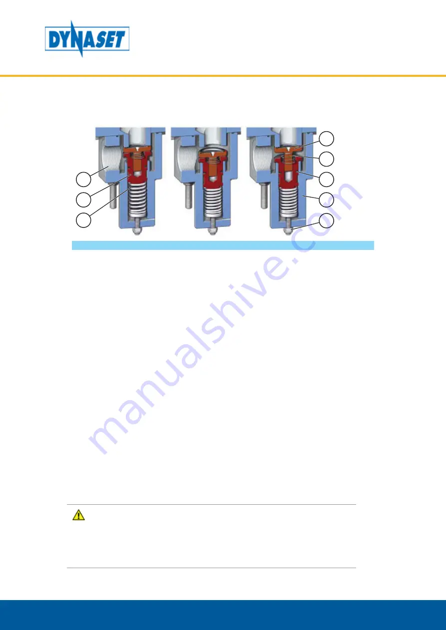
Picture 14: Operating principle of minimum pressure valve

A.  MPV closed
B.  MPV open

C.  MPV open, non-re-

turn valve closed.

1.  Non-return valve plate
2.  Non-return valve spring
3.  Seal
4.  Pressure holding valve piston

5.  Pressure holding valve spring
6.  Pressure holding valve housing
7.  Adjustment screw / counternut 

(only in HKR500 and HKR7500)

8.  Compressed air connection

The minimum pressure valve is used as a:

Pressure holding valve

When there is no counter-pressure in air supply line, it prevents the pressure from 

dropping below the minimum pressure set at the pressure holding valve (factory 

setting approximately 5.5 bar). This pressure is necessary to ensure the oil supply 

to the compressor. At the same time this is the condition for good oil separation.

Non-return valve

It prevents compressed air flowing back from the system. This valve operates 

automatically.

ATTENTION!

The minimum pressure valve is not an over-flow valve for continuous 

operation (it is only used for the starting sequence until the higher 

operating pressure is reached and subsequently determines a higher 

system pressure).

Summary of Contents for HKR 1300

Page 1: ...rev 1 1 HKR 500 HKR 800 HKR 1300 HKR 2000 HKR 2500 HKR 4000 HKR 5000 HKR 7500 Download PDF version from www Dynaset com manuals Keycode MQT36Y HYDRAULIC SCREW COMPRESSORS USER MANUAL...

Page 2: ......

Page 3: ...ATION SYSTEM OF COMPRESSOR 17 3 3 PRESSURE AND COMPRESSION RATIO 17 3 4 INTAKE VALVE 18 3 4 1 FUNCTIONAL PRINCIPLE OF PNEUMATIC INTAKE CONTROL 19 3 5 MULTIBLOCK 20 3 6 OIL NON RETURN VALVE 22 3 7 AIR...

Page 4: ...HE COMPRESSOR 44 6 MAINTENANCE 45 6 1 MAINTENANCE INTERVALS 46 6 2 HYDRAULIC FLUIDS 46 6 3 COMPRESSOR OILS 47 6 3 1 MULTI GRADE OIL 48 6 3 2 TEMPERATURES AND OIL TYPES 48 6 4 CLEANING THE COMPRESSOR 4...

Page 5: ...ystem with Load Sensing variable displacement pump 29 Picture 19 Closed centre hydraulic system with Load Sensing variable displacement pump 30 Picture 20 Connection figure for closed centre hydraulic...

Page 6: ...Dynaset Oy Menotie 3 FI 33470 Yl j rvi Finland tel 358 3 3488 200 info dynaset com www dynaset com HYDRAULIC SCREW COMPRESSORS TABLE OF PICTURES...

Page 7: ...ty compressed air and it can be installed in almost any working machine HKR compressors are used topowerforexamplepneumatictools fillingtires airflushing purgeairprotection equipments cleaning equipme...

Page 8: ...PRESSORS GENERAL 1 3 TYPE PLATE Picture 2 Type plate The products type plate shows the following information 1 Product identification key 2 Product code 3 Serial number 4 Maximum hydraulic flow 5 Maxi...

Page 9: ...Finland tel 358 3 3488 200 info dynaset com www dynaset com 9 HYDRAULIC SCREW COMPRESSORS GENERAL 1 4 HKR COMPRESSOR LINE UP Picture 3 HKR compressor line up 1 HKR 500 HKR 800 2 HKR 1300 HKR 2000 HKR...

Page 10: ...lve 3 Hydraulic motor 4 Temperature probe connection 5 Lifting eyes 6 DYNASET type plate 7 Intake filter 8 Air pressure control valve 9 Oil thermostat 10 Oil filler cap 11 Heat exchanger 12 Heat excha...

Page 11: ...severe injuries Always wear appropriate clothing and safety equipment Couplings valves and hoses need to be kept tight and clean to avoid possible leakages Leaks in the hydraulic system must be repair...

Page 12: ...the compressor beware of unit parts warmed by hot hydraulic oil WARNING RISK OF BURNS Parts of the unit oil and oil filler cap can be hotter than 80 C Wear personal safety equipment Never aim compress...

Page 13: ...ean This is important to ensure safe reliable and longlife operation of your equipment Hydraulic system of a base machine should be maintained according to the service program 2 5 WARNING LABELS Warni...

Page 14: ...14 Dynaset Oy Menotie 3 FI 33470 Yl j rvi Finland tel 358 3 3488 200 info dynaset com www dynaset com HYDRAULIC SCREW COMPRESSORS SAFETY...

Page 15: ...rication 1 The screws of screw compressor are driven by hydraulic motor The rotation of screws creates suction and air starts to flow 2 The air flows through intake filter and valve into the compressi...

Page 16: ...n the oil temperature the oil thermostat valve routes the oil flow through the oil cooler or directly to the oil filter Optimum operating temperature of oil is adjusted by integrated thermostat valve...

Page 17: ...ng grooves to the surfaces to be lubricated Separate oil pump is not needed 2 HERMETIZATION Injected oil seals screw surfaces against each other 3 COOLING DYNASET HKR screw compressor is equipped with...

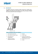
Page 18: ...TING PRINCIPLES 3 4 INTAKE VALVE The Dynaset HKR is equipped with an integrated intake valve that is mounted directly on the compressor housing It is triggered via air pressure control valve 1 1 2 Int...

Page 19: ...pressure at the air pressure control valve is reached the pilot air blue in the picture closes the intake valve When the intake valve is closed compressor is in standby mode When the air in air supply...

Page 20: ...e air oil separating elements the minimum pressure valve the non return valve with the oil return line and the oil return line check are integrated 1 5 4 6 3 2 9 8 7 HKR 1300 2500 Picture 10 Multibloc...

Page 21: ...HKR 5000 7500 HKR 4000 Picture 11 Multiblock of HKR 4000 and HKR 5000 HKR 7500 1 Air oil separating element s 2 Oil circulation connection Inlet 3 Oil circulation con nection Outlet 4 Oil return line...

Page 22: ...l non return valve prevents oil flooding from air oil separating element s The oil tend to flow from air oil separating element s to screw compressor due to the pressure difference in the system when...

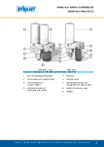
Page 23: ...ibuted residual oil form air The air to the vertical cartridge comes from below The residual oil is separated from the air while flowing through the filter element Filtered oil flows back to oil circu...

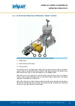
Page 24: ...d air connection The minimum pressure valve is used as a Pressure holding valve When there is no counter pressure in air supply line it prevents the pressure from dropping below the minimum pressure s...

Page 25: ...R The filter mesh size is 20 m The filter has a bypass valve which opens when oil is cold and high viscosity or when the filter is heavily soiled and pressure difference is 2 5 bar This allowes oil fl...

Page 26: ...the oil filter and is accessible from the outside left side viewed from the drive side The oil thermostat opens the connection to the heat exchanger when the operating temperature is reached The oil t...

Page 27: ...pe of hydraulic systems Most common hydraulic systems in mobile machinery are Open centre hydraulic system with Load Sensing variable displacement pump Closed centre hydraulic system with Load Sensing...

Page 28: ...re hydraulic system with Load Sensing variable displacement pump In open centre hydraulic system the flow is returned to tank through the control valves open centre that is when the control valve is c...

Page 29: ...Picture 18 Connection figure for open centre hydraulic system with Load Sensing variable displacement pump 1 DYNASET hydraulic equipment 2 DYNASET Priority valve PV SAE 2 1 DYNASET PC SAE pressure com...

Page 30: ...NT PUMP Picture 19 Closed centre hydraulic system with Load Sensing variable displacement pump In a closed centre hydraulic system the oil flow is stopped from the pump when control valve is centered...

Page 31: ...7 6 8 1 2 5 P CF T LS T P Picture 20 Connection figure for closed centre hydraulic system with Load Sensing variable displacement pump 1 DYNASET hydraulic equipment 2 DYNASET LSV Load sensing valve 3...

Page 32: ...TION HYDRAULIC SYSTEM WITH FIXED DISPLACEMENT PUMP Picture 21 Hydraulic system with fixed displacement pump In hydraulic system which has the fixed displacement pump the oil flow from the pump is fixe...

Page 33: ...LS 4 2 1 6 5 7 1 2 2 3 2 Picture 22 Connection figure for hydraulic system with fixed discplacement pump 1 DYNASET hydraulic equipment 2 DYNASET Priority valve PV SAE 2 1 DYNASET PC SAE pressure compe...

Page 34: ...igned to enable easy installation of your DYNASET hydraulic product DYNASET LOAD SENSING VALVE Picture 23 Load sensing valve LSV DYNASET LSV load sensing valves are made for installations in a closed...

Page 35: ...icture 25 Placing the HKR compressor NOTE When positioning the HKR compressor note the maximum inclinations and ensure that required oil cooling capacity of hydraulic system is sufficient READ CHAPTER...

Page 36: ...run the unit At least the minimal flow must be available READ CHAPTER 10 TECHNICAL SPECIFICATIONS for hydraulic flow requirements of your HKR compressor minimal IN OUT NOMINAL FLOW L min MIN MAX Pictu...

Page 37: ...ydraulic system PSI BAR PRESSURE MIN 5 70 MAX 5 bar Picture 29 Return line connection ATTENTION Ensure that the filtering degree and cooling capacity of the hydraulic system are sufficient READ CHAPTE...

Page 38: ...itting and cut off valve options Picture 31 Air supply system connection The inner diameter of pipe hose used for compressor s connection should be at least equal to AP port to keep the pressure drop...

Page 39: ...filled with oil The compressor is delivered with compressor oil Only in special cases compressor is delivered without compressor oil The oil level must be between min and max MAX MIN Picture 33 Oil l...

Page 40: ...rox a half of the nominal value The nominal discharge is achieved when the compressor is rotated by hydraulic flow adequate to the nominal rotation speed When compressor is running oil circulation is...

Page 41: ...ressor must not be used as breathing air even if purified and filtered Picture 35 Compressed air must not be used as breathing air HKR compressor is designed to compress athmospheric air only and must...

Page 42: ...Y N T H E T I C MAX MIN 0 45 0 15 15o C 45o C Picture 37 Operating in extreme ambient temperatures 5 4 AIR HUMIDITY Compressor can be operated at the relative humidity up to 90 provided that the ambi...

Page 43: ...opened When the compressed air is consumed off load automatic controls the intake valve according to the current air demand 5 6 COLD STARTS When starting the compressor in cold conditions ambient temp...

Page 44: ...33470 Yl j rvi Finland tel 358 3 3488 200 info dynaset com www dynaset com HYDRAULIC SCREW COMPRESSORS OPERATION 5 7 STOPPING THE COMPRESSOR To stop the compressor shut off the hydraulic flow Picture...

Page 45: ...dance with a service program ATTENTION Before beginning any maintenance or repair ensure that the system is stopped and depressurized Make sure that the system can not start accidentally STOP Depressu...

Page 46: ...he air oil separating element x Change oil and oil filter x o Check change if necessary x Change NOTE All installation and service of must be performed by experienced personnel only 6 2 HYDRAULIC FLUI...

Page 47: ...rating conditions such as pollution of the intake air and also in case of high ambient temperatures Petroleum raffinates mineral oils synthetic oils as well as bio degradable oils can be used as screw...

Page 48: ...sity class and a thermal stability is no longer completely ensured Therefore the use of multi grade oils in DYNASET HKR compressors is not authorized Only use oils approved for screw compressors Use t...

Page 49: ...l Corena 4S R 2500h or 12 months Shell 46 68 Synthetic oil Castrol Aircol SR 2500h or 12 months Shell 46 68 Synthetic oil Rarus SHC 1020 2500h or 12 months Exxon Mobil 46 68 Synthetic oil 6 4 CLEANING...

Page 50: ...nfo dynaset com www dynaset com HYDRAULIC SCREW COMPRESSORS MAINTENANCE 6 5 OIL LEVEL CHECK Location of oil filler cap HKR 500 800 HKR 1300 2500 HKR 4000 HKR 7500 HKR 5000 Picture 43 Location of oil f...

Page 51: ...ler cap and check the oil level If required fill up with the same oil as in the HKR compressor up to the maximum level O I L MAX MIN NOTE Hot oil expands in volume As a result oil may escape when the...

Page 52: ...l change NOTE Make sure to use recommended screw compressor oil Add oil of the same oil type from the same manufacturer Switching over to another oil type can require flushing of the compressor block...

Page 53: ...set com HYDRAULIC SCREW COMPRESSORS MAINTENANCE 2 Open the oil drain plug with allen key 3 Drain the used oil to a suitable container clean the oil drain plug and put it back MAX 70 Nm 4 Replace the o...

Page 54: ...NTENANCE 6 Close the oil filler cap firmly onto the filler neck by hand 7 Start the compressor and close the supply line Allow compressor run for three minutes START 3min 8 Stop the compressor and wai...

Page 55: ...iller cap check the oil level fill and top up the missing oil quantity again up to the maximum level if required O I L MAX MIN 6 7 REPLACING OIL FILTER The oil filter must be replaced at every oil cha...

Page 56: ...r cartridge with clean oil or grease Fill the cartridge with the same oil as in the HKR screw compressor O I L OIL 3 Insert the new oil filter cartridge onto the multiblock and tighten by hand Use of...

Page 57: ...till STOP 1min 6 Check the oil level fill up the missing oil quantity up to the maximum level O I L MAX MIN 6 8 REPLACING AIR OIL SEPARATING ELEMENT S ATTENTION Dispose of the old separating element i...

Page 58: ...HYDRAULIC SCREW COMPRESSORS MAINTENANCE 1 Remove the air oil separating element s with a suitable tool 2 Lubricate the seal of the new air oil separating element with clean oil or grease OIL 3 Insert...

Page 59: ...it run for 3 minutes Check the compressor and system for leaks when the system is running 3min 6 9 REPLACING AIR FILTER ELEMENT ATTENTION Dirt and dust particles must be prevented to get into the air...

Page 60: ...200 info dynaset com www dynaset com HYDRAULIC SCREW COMPRESSORS MAINTENANCE 2 Remove dust carefully from the filter housing 3 Insert new filter element and install filter cover ATTENTION Dispose the...

Page 61: ...l j rvi Finland tel 358 3 3488 200 info dynaset com www dynaset com HYDRAULIC SCREW COMPRESSORS MAINTENANCE 6 10 ADJUST THE OFF LOAD PRESSURE 1 Loosen locking nut and use adjust knob to set off load p...

Page 62: ...nt Adjust if necessary Check the hydraulic motor of compressor for possible leakage Replace shaft seal if necessary Air pressure in delivery line prevents compressor start Check and depressurize air d...

Page 63: ...ACTION Compressor does not produce compressed air Delivery line is closed Check Air pressure control valve failure or incorrect setting i e adjusted pressure is lower than setting of minimum pressure...

Page 64: ...pass valve Check Replace heat exchanger by pass check valve if necessary Insufficient cooling capacity Check Improve cooling capacity if necessary Dynaset oy offers wide range of hydraulic components...

Page 65: ...tion of intake control valve Check control valve anv control valve flap clean the bearing and guides chek stroke replace if necessary Leaks in system Check Seal if necessary FAILURE REASON CORRECTIVE...

Page 66: ...66 Dynaset Oy Menotie 3 FI 33470 Yl j rvi Finland tel 358 3 3488 200 info dynaset com www dynaset com HYDRAULIC SCREW COMPRESSORS MAINTENANCE...

Page 67: ...t primary to the seller of the product Contact must be made as soon as possible latest thirty 30 days after the problem was identified Seller and or manufacturer technical staff determines the nature...

Page 68: ...ack of maintenance Cost of maintenance adjustments installation or startup Coating hydraulic oil quick couplings and interconnection hoses internal or external to system assemblies Products altered or...

Page 69: ...y responsible way Do not dispose used oils electrical components batteries or any other hazardous waste with normal waste They are harmful for the environment and can be recycled for re use Contact yo...

Page 70: ...70 Dynaset Oy Menotie 3 FI 33470 Yl j rvi Finland tel 358 3 3488 200 info dynaset com www dynaset com HYDRAULIC SCREW COMPRESSORS PRODUCT DISPOSAL...

Page 71: ...directive 2006 42 EC LVD directive 2006 95 EC EMC directive 2004 108 EC Applied conformity standards CEN EN ISO 4413 EN ISO 4413 2010 Hydraulic fluid power General rules and safety requirements for s...

Page 72: ...72 Dynaset Oy Menotie 3 FI 33470 Yl j rvi Finland tel 358 3 3488 200 info dynaset com www dynaset com HYDRAULIC SCREW COMPRESSORS DECLARATION OF CONFORMITY...

Page 73: ...89 40 10 57 55 14 53 80 21 13 105 27 74 140 36 98 200 52 83 Pressure at nominal flow bar psi 123 1 84 135 1 58 205 2 73 205 2 73 205 2 73 215 3 18 210 3 46 230 3 36 Pressure max bar psi 230 3336 230...

Page 74: ...Dynaset Oy Menotie 3 FI 33470 Yl j rvi Finland tel 358 3 3488 200 info dynaset com www dynaset com 74 HYDRAULIC SCREW COMPRESSORS TECHNICAL SPECIFICATIONS...

Page 75: ...DYNASET OY all rights reserved...

Page 76: ...tepumppu JPL J teastioiden pesulaite HSP Hydrauliset uppopumppu PAINEILMA HK Hydrauliset m nt kompressori HKL Hydrauliset lamellikompressori HKR Hydrauliset ruuvikompressori MAGNETOINTI HMG PRO Hydrau...

Reviews: