Rev. 01/11
- 2.13 -
TFXL-X
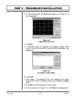
3. On the pop-up screen, click
Next
button twice to get to Page 3 of 3.
See
Figure 2.8
.
4. Click
Edit
.
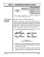
5. If calibration point is displayed in Calibration Points Editor
screen, record the information, highlight and click
Remove
. See
Figure 2.9
.
6.
Click
ADD…
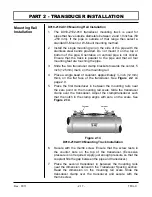
7. Enter Delta T, Uncalibrated Flow, and Calibrated Flow values
from the DTTS/DTTC calibration label, the click
OK
. See
Figure
2.10
.
8. Click
OK
in the Edit Calibration Points screen.
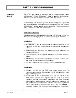
9. Process will return to Page 3 of 3. Click
Finish
. See
Figure 2.8
.
PART 2 - TRANSDUCER INSTALLATION
Figure 2.8
Calibration Page 3 of 3
Figure 2.9
Calibration Points Editor
Summary of Contents for TFXL series
Page 2: ......
Page 10: ...Rev 01 11 1 8 TFXL X PART 1 TERMINOLOGY PC INTERFACE CABLE ...
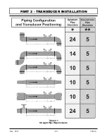
Page 23: ...Rev 01 11 2 3 TFXL X PART 2 TRANSDUCER INSTALLATION Table 2 1 Straight Pipe Requirements ...
Page 52: ......
Page 53: ...APPENDIX ...
Page 54: ......
Page 55: ......
Page 69: ......

