5.25”
Green engine
block ring
Green engine block
ring inside tube
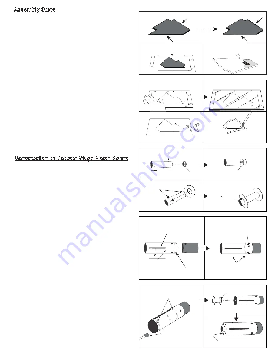
Place centering rings
between the marks
on the tube
Apply a line of glue around
the tube here
Step 5
Align the holes when
glueing together
Make sure to remove these
square pieces with a
hobby knife first
Inside of tube
Booster tube
Place glue on the inside
edge of tube here
Step 7
Assembly Steps
Construction of Booster Stage Motor Mount
1.
(Optional to reduce drag)
Sand the balsa laser-cut
sheets using 200 grit sandpaper. Then remove the fins
with a hobby knife and airfoil the front and rear edges.
2.
(Optional for Fin Skins)
Fin skins are highly rec-
ommended to survive a hard landing.
Place a piece
of regular paper on top of a smooth surface (wood or
glass). Then place a fin on top of the paper.
3.
(Optional Fin Skins)
Mix glue with water in a small
cup (the right mixture should be watery enough to
avoid leaving brush marks when painting the fin). Use
a paintbrush to apply a thin layer of the mixture to one
side of the fin. Once complete, flip over the fin (press
into the paper you placed in the prior step) and paint
the mixture onto the opposite side.
4.
(Optional Fin Skins)
Place a piece of paper over
the top of the fin. Press down on the paper to rub out
any bumps in the paper to smooth out the surface of
the fin. Place wood or glass on top of the paper and
then place some books or weight on top and let dry.
Once dry, cut out the fin from the paper and trim away
the overlap with a hobby knife. Repeat this process for
all 6 fins.
The booster stage is the lowest section of the rock-
et. It is designed to fall off and tumble back to the
ground after the engine burns out during the flight.
5. The
booster stage engine mount tube
is the short-
er 29mm tube that is 5.25in (133mm) long, and it has a
small rectangular cutout at one end of the tube. Locate
one of the green rings (CR 24/29). Using a wood dow-
el, spread a line of glue inside the tube at the cut-out
location. Slide the green ring inside the tube so it is
visible through the cut-out window of the tube. Wipe off
any glue that oozes out with a paper towel
6. Test fit both large wooden CR 29/2.6" centering
rings onto the
motor mount tube
. Sand the inside of
the rings if necessary. Now spread a thin line of glue
around the inside edge of one of the tube line mark-
ings. Then slide one of the rings over the glue and rest
it just behind the tube mark. Repeat step for the other
centering ring. Clean off excess glue and let dry. Set
aside the motor mount for now.
7. Add a ring of glue to the inside forward edge of the
booster tube.
Then
take the
red tube coupler
with
the holes in it and slide it into the
booster tube
. Take
care to align the holes in both tubes. Wipe away any
excess glue on the inside and the outside of the tubes.
8. Use a wood dowel to spread two lines of glue inside
the
booster tube
; one line of glue on each side of the
slots cut in the tube. Now slide the
motor mount
into
the
booster tube
(into the end with no coupler). The
motor mount
will stop against the inside end of the
coupler, clean off any excess glue. Apply a fillet
of glue around the edge of the back ring.
Place a single fin on a large piece
of regular printer paper
Air-foil the fins by rounding out top and bottom edges
with sand paper
Use painbrush to brush on
the glue
Use wood dowel to place a
glue ring at these areas
inside the tube
Insert the end with the engine
block into the booster tube first
Wood dowel with glue
Apply a glue fillet here
Step 8
Smooth the fin under the top
& bottom layers of paper
Glass over the top
When dried, cut out fin
Trim edges of paper off of the
fin with a hobby knife
Page 2
Step 2
Step 4
Step 1
Step 3
Step 6


