dynaTron® 25 serIes PhysICal feaTures
DYNATRON® 25 SERIES™ | OPERATOR’S MANUAL
14
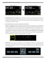
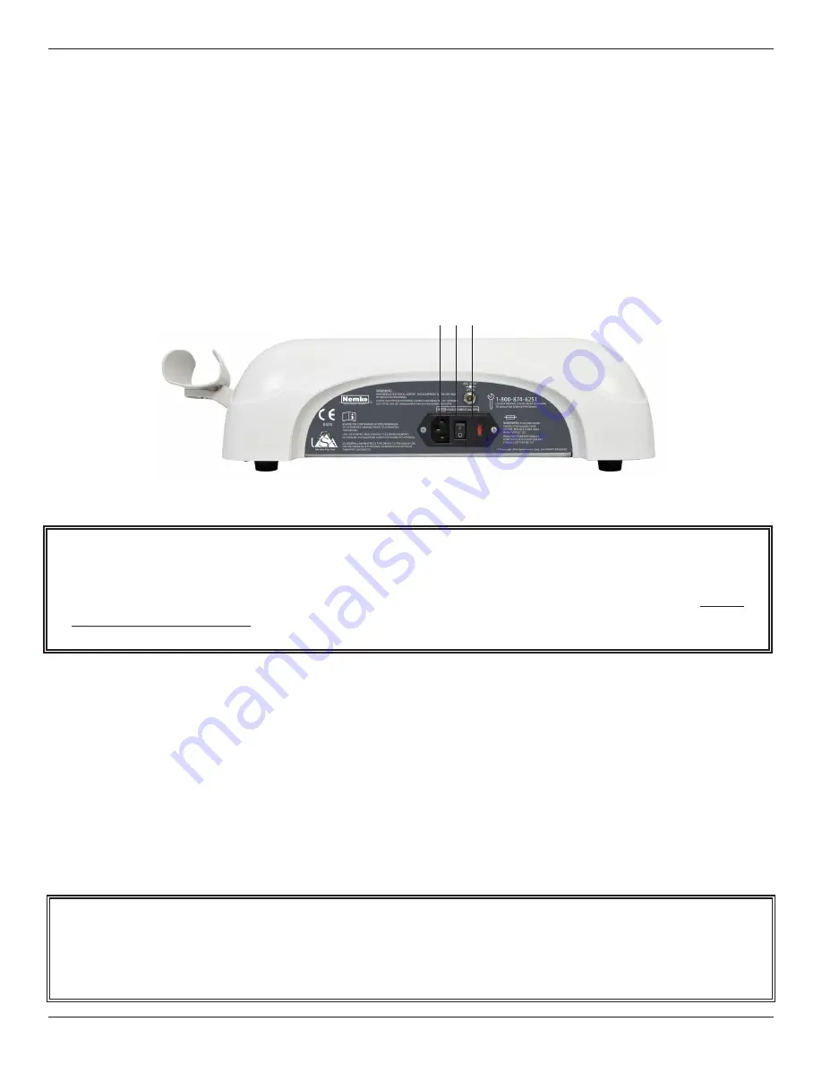
Back Panel Jacks
a. POWER CORD ENTRY MODULE. This entry module is designed to accommodate a hospital-grade
power cord.
b. Power 1/0 (ON/OFF) Switch. Located on the back of the unit this switch is labeled “1” and “0.” Set the switch
to “1” for ON; set the switch to “0” for OFF.
c. Battery. This jack may be used to supply power to the device using an optional battery pack. More information
about the optional battery operation is provided later in this manual.
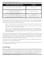
Current Limit
The Dynatron 25 Series devices continuously measure the actual current output during IFC and Premod treatments and
limit the output current to the level set for the device. As the intensity of a treatment is increased the current output is also
increased.
When the maximum output current limit is reached, the device will immediately stop increasing the intensity and
automatically reduce the intensity a few increments to prevent the possibility of patient discomfort. Simultaneously, the
device will beep and one of the following CURRENT LIMIT WARNINGS will appear in the lower right-hand corner of the
Treatment Display Screen. Following is a list of CURRENT LIMIT WARNINGS that may occur.
NOTE: Patient Remote Stop. Adding the Remote Stop requires a custom order. The Patient Remote Stop Jack is
located below the Light Probe holder. The remote stop is controlled by the patient during unattended therapy, allowing
the patient to stop the treatment at any time. When the button on the remote stop cable is pressed, output for all Stim
modalities and pad treatments is stopped. During Combo treatments, both Sound and Stim outputs are stopped.
Back Panel Jacks
a b c
Remember to treat at the patient’s comfort level. It is not important to reach a given intensity level. It is only
important to set the treatment at a level that is comfortable to the patient. See “Electrotherapy Usage Cautions” in
this manual for suggested intensity limits.

