dynaTron® TherMosTIM™ Probe
DYNATRON SOLARIS
®
PLUS SERIES | SERVICE MANUAL REV. 6 | AUGUST 29, 2017
96
ThermoStim Probe Detailed Setup
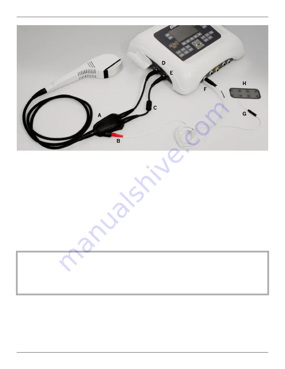
1. Connect ThermoStim Probe
Connect the two ThermoStim cables as follows:
(1) Plug the cable with the serrite Bead (C) into the Light Probe Jack (E) located on the left side of the console.
Note. The 707 is designed with Light Probe/Pad Jacks on both sides of the console. Either set of Jacks may
be used when setting up a ThermoStim Probe Treatment.
(2) Plug the remaining cable into the Light Pad Jack (D).
2. Connect Combo Leads
Connect the three lead ends as follows:
(1) Plug the Red Banana Pin (B) into the “Y” Box receptacle as shown.
(2) Plug the stereo plug (F) into one of the available channel jacks located on the front of the Solaris Plus console.
(A) “Y” Box (B) “Red” Banana Pin (C) Ferrite Bead (D) Light Pad Jack (E) Light Probe Jack (F) Stereo Plug (G) Combo Leadwire (H) Electrode
Note: The two ThermoStim cables have “Keyed and Locking” connectors. When inserting the connectors, carefully align
the arrows appearing at the top of both the jack and the connector. Once the arrows are aligned, the two will slide together
smoothly and exactly. Do not force the connector or damage to the pins may occur. When removing the connectors,
turn the connector’s outer sleeve in the direction of the arrow and the connector will slide easily away from the jack.

