background image

InsTallaTIon and feaTures

DYNATRON® T3™ HI-LO TREATMENT TABLE & T4™ TRACTION TABLE  |  OPERATOR’S MANUAL REV. 10 | 4/4/2018

3

Installation  

and Features

Unpacking

Upon receiving the table, immediately unpack it and verify that all parts and accessories are included. Check for possible 
damage, obvious or concealed. In case of damage, immediately notify the freight carrier and take any steps necessary to file a 
claim for the damage sustained. If possible, reuse the shipping carton if the table must be shipped for any reason. The carton 
is specially designed to protect the table from shipping damage. Improper packaging of the unit during transport can result 
in damage and invalidate the warranty.

Complete the warranty registration form located at the back of this manual and return it to Dynatronics within 30 days 
of purchase. This is essential to insure you are not billed for services that are covered by the warranty policy. Warranty 
registration should include all applicable serial numbers.

Setup

•  After unpacking, set the table in the desired location.  No assembly is required as the table is fully assembled and all 

motors are pre-adjusted at the factory.  

•  Provide ample clearance around and above the table.  

•  Securely lock all four casters for stability.  Install the traction arm for the T4 table (see instructions on the following 

page). Inspect all cables and power cord for damage; 

•  Immediately report any damage found to Dynatronics’ Customer Service (800) 874-6251.

Summary of Contents for Dynatron T3

Page 1: ...O P E R A T O R S S E R V I C E M A N U A L ...

Page 2: ...urposes It can be utilized as a treatment table with surfaces that can be adjusted to various positions or it can be used in conjunction with Traction devices and Traction accessories such as belts and harnesses to exert therapeutic pulling forces on the patient s body 890 5900 primarily for the cervical lumbar areas Inventory T34MANUAL Rev 10 ISO 13485 DNV GL NEMKO PRESAFE AS CERTIFIED Dynatron T...

Page 3: ...g the Table Height 6 Adjusting Head and Foot Sections 6 Positioning the Patient 6 Warnings and Precautions 7 Technical Information 8 General Specifications 8 Disposal of Equipment and Accessories 8 Environmental Conditions Transport and Storage 9 Definition of Symbols and Labeling 9 Symbols and Labels 10 Cleaning Naugahyde Surfaces 10 Maintenance and Service 12 General Maintenance 12 Components an...

Page 4: ...les include all of the standard advantages of Dynatronics engineering with meticulous attention to detail and quality producing a reliable product that will provide years of excellent performance Outstanding features include Dual Full Length Foot Switches Postural Drainage Optional Motorized Mid Section MSAS Mobilization Strap Attachment System Easy Glide Foot Section with Positive Dual Lock Conto...

Page 5: ...nable mobility and dexterity to monitor patient responses to attended or unattended treatments Before You Treat a Patient Before administering a treatment to a patient familiarize yourself with the operating instructions as well as the contraindications warnings and precautions associated with the use of treatment tables and the associated Traction Treatments In addition to this information consul...

Page 6: ...transport can result in damage and invalidate the warranty Complete the warranty registration form located at the back of this manual and return it to Dynatronics within 30 days of purchase This is essential to insure you are not billed for services that are covered by the warranty policy Warranty registration should include all applicable serial numbers Setup After unpacking set the table in the ...

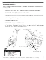
Page 7: ...the Nylon Washer 29 onto the Pivot Pin 28 before sliding it through center hole in the adjustment plate 4 Continue sliding the Pivot Pin through the lower traction arm Pivot Pin hole 5 Attach the second nylon washer 29 6 Slide the Pivot Pin through the hole in the Lower frame 7 Securely tighten the Nylon Lock Nut 30 to the end of the Pivot Pin 28 Do not over tighten the Nylon Lock Nut 30 When it f...

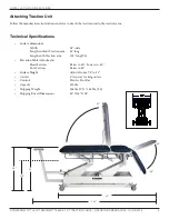
Page 8: ...ical Specifications Surface dimensions Width 28 wide Length without Traction arm 81 long Length with Traction arm 105 long T4 Elevation Table Adjustments Head Section Raises to 40 Lowers to 80 Foot Section Raises to 85 Surface Height Adjusts from 17 5 to 39 Casters 4 two way locking casters Controls Electric Foot Bar Capacity 500 lbs Shipping Weight 348 lbs T3 385 lbs T4 Shipping Boxed Dimensions ...

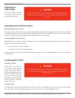
Page 9: ...ction Lever moves counterclockwise As long as the lever is down the section will continue to move down When the handle is released the section will securely remain in place Positioning the Patient Ambulatory Patients Verify that the casters are locked before positioning the patient Adjust table height so that the patient platform is just below the patient s buttocks The patient should always be se...

Page 10: ...the patient prior to making any adjustments to the table while the patient is positioned on the table 5 DO NOT change the angle of any section while the patient s weight is on that section 6 ALWAYS keep children away from the table 7 DANGER Risk of explosion hazard if used in the presence of flammable anesthetics 8 Verify that the casters are locked before treating the patient WARNING PINCH POINTS...

Page 11: ... Maximum Leakage 100 µa or less Typ 18 µa Grounding Characteristics Resistance from ground pin on power plug to exposed metal surfaces 1 Ohm or less Typ 08 Ohms Disposal of Equipment and Accessories There is no risk posed in disposal of this equipment or its accessories This product contains no hazardous materials CAUTION To ensure proper mechanical operation a daily check and preliminary operatio...

Page 12: ...the following ranges a an ambient temperature range of 40 C b a relative humidity range of 10 to 100 including condensation c an atmospheric pressure range of 500 hPa to 1060 hPa Definition of Symbols and Labeling Some or all of the following symbols are included in the labeling for this device Definitions accompany each symbol Caution Warning Follow Instructions for Use Made in USA Temperature Mo...

Page 13: ... Engineered Products offers the following cleaning instructions for their Naugahyde products Naugahyde with Advance BeautyGard has been formulated to achieve a superior level of disinfectability with disinfectant products containing sodium hypochlorite common household bleach diluted 1 10 Dampen a soft white cloth with a solution of household bleach sodium hypochlorite 10 bleach 90 water Rub gentl...

Page 14: ...E T4 TRACTION TABLE OPERATOR S MANUAL REV 10 4 4 2018 11 Unapproved Cleaning Solutions Strong Phenols Phenol Alcohol Combinations Sodium Hypochlorite Household Bleach Sodium Bromide Citric Acids Iodophors Ammonium Chloride Accelerated Hydrogen Peroxide 0 5 ...

Page 15: ...ent at 1 800 874 6251 NOTE Only technically qualified personnel should attempt to service or repair this equipment GENERAL MAINTENANCE If the bed is located in an area where it is subject to extreme amounts of moisture humidity or dust the pivot joints and sliding surfaces should be cleaned and lubricated WARNINGS An electric shock hazard may exist when electrical covers have been removed In addit...

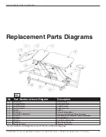
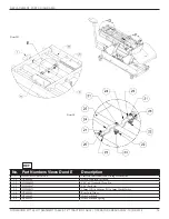
Page 16: ...asters 11 T34MPH Main Plug in Housing 12 40 106 Magnetic Motor Max 65 Main Motor 13 40 106 B Magnetic Mid Lift Motor Max 10 14 T34MSL Mid Lift Switch Left 15 T34MSR Mid Lift Switch Right 16 DP000088 Mid Section Gatch Mechanism Spring 17 DP000061 Master Gatch Mechanism Wieldment controls all three sections 18 T4FOOTSWITCH Foot Switches 19 T34FSC Foot Switch Cable 20 DP000084 Slide Rack Block Assemb...

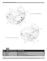
Page 17: ...n 3 T4 TOP color B Top Mid Section 4 T4 TOP color C Top Foot Section 5 DT4PB Pull Bar 6 DTKNOB Lift back Handle black 7 T4SLIDELOCKHANDLE Traction Arm Handle and Sliding Mechanism 8 DP000075 Mobilization Strap Attachment System Chrome Bar 9 DP000072 Foot Switch Bar 10 DTCAS Two Way Locking Casters 11 T34MPH Main Plug in Housing 12 Pinch Point Labels Warning Pinch Points See part numbers and diagra...

Page 18: ...2 40 106 Magnetic Motor Max 65 Main Motor 12 40 106 A Magnetic Motor Max 63 Main Motor used in conjunction with Mid Lift Motor in place of the Max 65 13 40 106 B Magnetic Mid Lift Motor Max 10 REF Right T3 Table with Mid Lift Motor Both the T3 and T4 Traction Tables are available with the Mid Lift Motor Left T4 Traction Table with standard main Motor ...

Page 19: ...rs View A Description 3 T4 TOP color B Top Mid Section 13 40 106 B Magnetic Mid Lift Motor Max 10 14 T34MSL Mid Lift Switch Left 16 35 005 Mid Section Gatch Mechanism Spring 17 DP000061 Master Gatch Mechanism Wieldment controls all three sections REF View A enhancement with Mid Lift Motor View A enhancement without Mid Lift Motor ...

Page 20: ...ATOR S MANUAL REV 10 4 4 2018 17 No Part Numbers View B Description 9 DP000072 Foot Switch Bar 16 DP000088 Mid Section Gatch Mechanism Spring 18 T4FOOTSWITCH Foot Switches 19 T34FSC Foot Switch Cable REF View B location of Z Spring applicable to both the T3 and the T4 tables Detail B ...

Page 21: ...E Description 7 T4SLIDELOCKHANDLE Traction Arm Handle and Sliding Mechanism 20 DP000084 Slide Rack Block Assembly 21 HW000022 3 16 x 1 Grooved Clevis Pin 22 HW000187 3 16 Push Nut 23 HW000171 12mm OD x 4 88mm ID x 1mm Thick Washer 24 DP000080 Bent Lock Hinge 25 DP000082 Slide Lock Shaft 26 DP000112 Slide Lock Shaft Spring REF Detail D Detail E ...

Page 22: ...OR S MANUAL REV 10 4 4 2018 19 No Part Numbers Views F Description 14 T34MSL Mid Lift Switch Left 15 T34MSR Mid Lift Switch Right 30 HW000017 3 8 16 Nylon Lock Nut 31 DP000106 Gatch Lock Spring with Mid Lift Motor only REF Detail F T4 with Mid Lift Motor Detail F T3 with Mid Lift Motor ...

Page 23: ...N TABLE OPERATOR S MANUAL REV 10 4 4 2018 20 No Part Numbers Views G H Description 27 DP000006 Traction Arm Assembly long 28 DP000099 Traction Arm Pivot Pin 29 HW000071 Nylon Washer 375 x 875 x 083 30 HW000017 3 8 16 Nylon Lock Nut REF View locations G H Detail G Detail H ...

Page 24: ...calling Dynatronics Customer Service to obtain an SVO or RMA 1 User name and address 2 User phone number 3 Serial number of the unit 4 A description of the problem with the unit After receiving the Service Order Number SVO or Return Material Authorization Number RMA write the number clearly on the outside of the shipping container Packaging and Shipping of Replacement Parts All defective or broken...

Page 25: ...e information that reasonably suggests a probability that a device caused or contributed to a death b serious injury or c serious illness If you receive information that reasonably suggests a device malfunction and a recurrence will probably cause a death b serious injury or c serious illness Definition of Serious Injury A serious injury is an injury that 1 is life threatening 2 results in permane...

Page 26: ...rvice under this warranty must be in the original shipping carton freight prepaid fully insured and or otherwise properly packed to prevent damage DYNATRONICS is not liable for any damage to the item while in transit Include a summary of the problem with the product Write the return authorization number obtained from DYNATRONICS on the shipping label SHIPPING COSTS Within the first 30 days of the ...

Page 27: ...tative I have read and understand the information contained in the operator s manual for this device I have received in service training from my dealer and or Dynatronics for the operation of this device IMPORTANT If there is anything about the operation or use of your Dynatronics product that you do not understand contact your dealer or Dynatronics for instruction As a trained medical practitione...

Reviews: