L I N X W I T H A T R A F L E X I N S T A L L A T I O N
Introduction
Linx with Atra Flex Installation for Model 424 Automotive Dynamometers
2
INTRODUCTION
Thank you for your interest Dynojet’s Automotive Dynamometers. Before installing
the Linx with Atra Flex system, please take a moment to read this guide for proper
installation procedures.
C
ONVENTIONS
U
SED
I
N
T
HIS
M
ANUAL
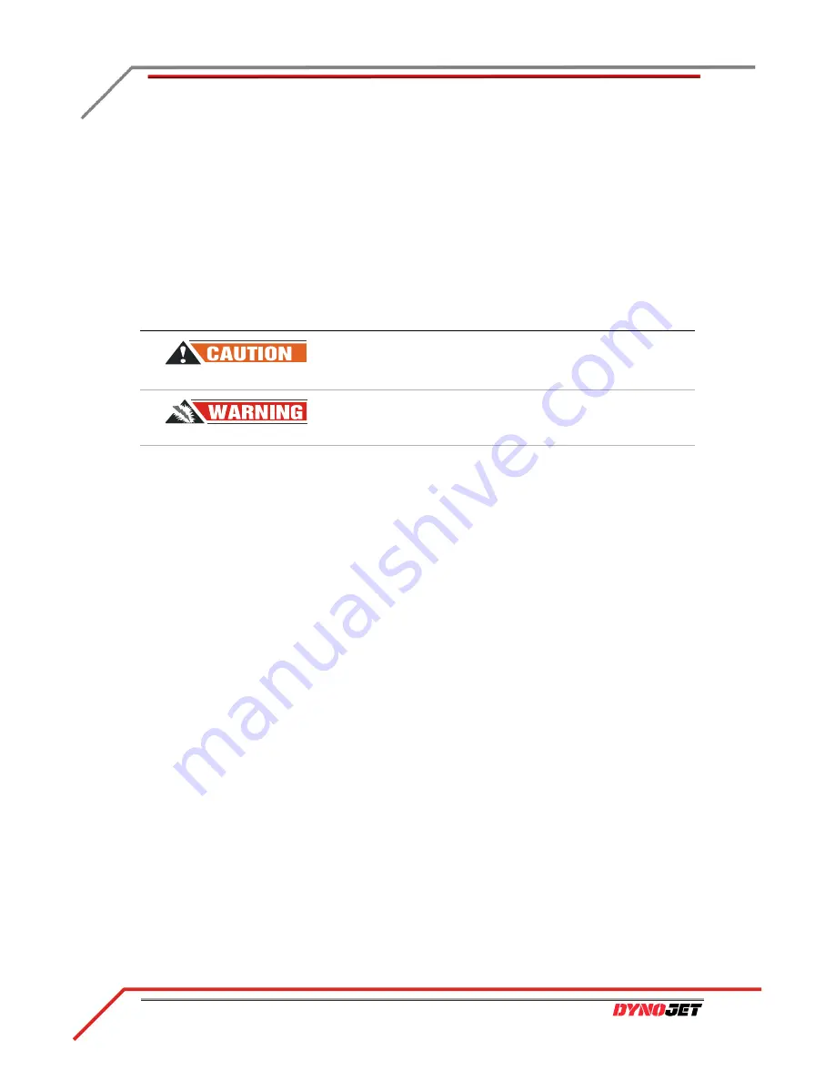
The conventions used in this manual are designed to protect both the user and the
equipment.
T
OOL
R
EQUIREMENTS
You will need to provide a drill and drill bit capable of drilling holes in concrete. Refer
to
for more information on installing Red Head Anchors.
• drill bit size: ½-inch
• minimum hole depth: 1
⅝
-inch (41.2 mm)
You will need to provide a long hex bit socket to tighten the bearing screws to the
torque specifications. Refer to
for more information on installing the
bearings.
• hex bit socket: ¼-inch
• minimum bit length: 1 ½-inch or longer
T
ECHNICAL
S
UPPORT
For assistance, please contact Dynojet Technical Support at 1-800-992-3525, or write
to Dynojet at 2191 Mendenhall Drive, North Las Vegas, NV 89081.
Visit us on the World Wide Web at
where Dynojet provides state of
the art technical support, on-line shopping, and press releases about our latest
product lines. Try our remote support assistance or watch one of our informative
videos. Stay informed about product releases and new map downloads by signing up
for the
Access the electronic version of this guide along with additional accessory guides,
software guides, and the latest technical bulletins at
www.dynojet.com/downloads
.
example of convention
description
The Caution icon indicates a potential hazard to the
dynamometer equipment. Follow all procedures
exactly as they are described and use care when
performing all procedures.
The Warning icon indicates potential harm to the
person performing a procedure and/or the
dynamometer equipment.
Blue
Highlights items you can click on directing you to a
location with additional information (electronic
version).


