

Product Overview
EFIS-D10A Pilot’s User Guide
2-3
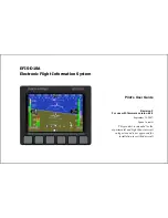
DISPLAY
The display is a 4-inch, 320 by 240 pixel, 450-nit LCD screen. It is acceptable to have the EFIS-D10A turned on during
engine start.
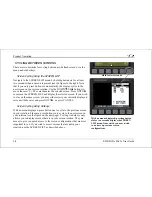
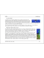
BUTTONS AND KNOBS
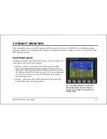
User interaction takes place via the six buttons along the bottom of the front panel of the unit.
When configured to control the EFIS-D10A, the HS34’s VALUE knob changes values when in various EFIS
menus and adjusts the barometer setting when no menus are displayed. The HS34’s HEADING and COURSE
knobs affect their respective parameters on the HSI page.
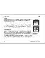
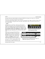
Theory of Operation
The primary flight instruments on your EFIS display are generated using a group of calibrated sensors. All of them are
solid state – that is, there are no moving parts. These sensors include accelerometers, which measure forces in all three
directions; rotational rate sensors, which sense rotation about all three axes; pressure transducers for measuring air data;
and magnetometers on all three axes for measuring magnetic heading.
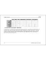
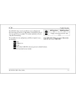
The table below describes which inputs and sensors are used within the EFIS to generate the different displayed
instruments. It is not meant to enable in-flight troubleshooting, but is provided to convey how much of an integrated
system your EFIS is.
Summary of Contents for EFIS-D10A
Page 2: ......
Page 8: ...Table of Contents viii EFIS D10A Pilot s User Guide Appendix D EFIS D10A Specifications 8 8...
Page 34: ......
Page 60: ......