
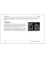


Available Pages
EFIS-D10A Pilot’s User Guide
4-3
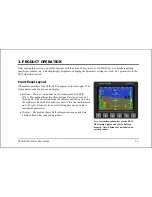
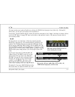
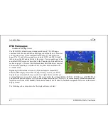
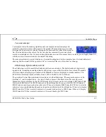
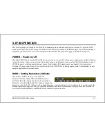
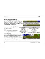
Horizon line, pitch and roll indicators
Bounded on the top by blue, and on the bottom by brown, the horizon line behaves in much the
same way as a traditional gyro-based artificial horizon. Unlike a mechanical artificial horizon,
the EFIS-D10A’s horizon has no roll or pitch limitation. The horizon line stays parallel to the
Earth’s horizon line regardless of attitude. The parallel lines above and below the horizon line
are the pitch indicator lines, with each line indicating 5 degrees of pitch. The end of each pitch
indicator line has a hooked barb that points towards the horizon line to aid attitude awareness.
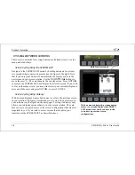
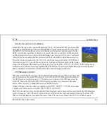
The roll scale has tic marks at 10, 20, 30, 45, 60, and 90 degrees of roll. In the CLUTTR menu
(described on page 5-8), you can choose between a stationary roll indicator and one that rotates
along with the horizon. The stationary roll indicator (type 1 in the EFIS > SETUP > CLUTTR > ROLL menu) has an
internal arrow which moves to stay perpendicular to the horizon. The moving roll indicator (type 2) rotates the scale
about a stationary internal arrow which points to the current roll angle on the scale.
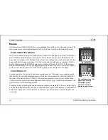
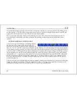
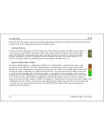
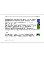
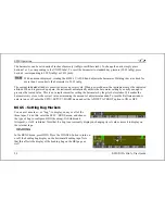
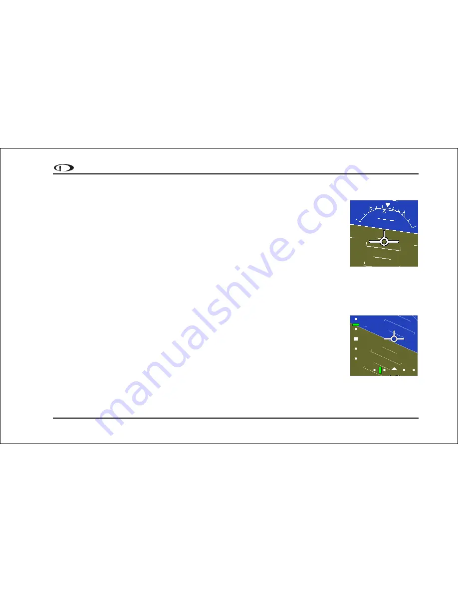
CDI/Glideslope Indicators
When the EFIS-D10A is receiving CDI or glideslope information from a GPS or nav radio, they
can be displayed on the main EFIS display as well as the on the full HSI page (as described in
the HSI Operation section on page 6-1). The data source is chosen on the HSI page using the
NAVSRC button; the EFIS and HSI CDI/GS displays are always synchronized to the same
source. There is no way to change the source on the EFIS screen.
On the EFIS page, these two items are enabled via the EFIS > SETUP > CLUTTR menu under
a single item, which can be set to either CDI:N, CDI:Y, or CDI+GS.
The CDI is located just above the slip/skid ball when displayed, and behaves much as described in the HSI Operation
section on page 6-1. The CDI needle is green when sourced from a nav radio and magenta when sourced from GPS.
When to/from information is available, the center of the CDI is an arrow; when on an ILS, it is a filled-in square.
Summary of Contents for EFIS-D10A
Page 2: ......
Page 8: ...Table of Contents viii EFIS D10A Pilot s User Guide Appendix D EFIS D10A Specifications 8 8...
Page 34: ......
Page 60: ......


