HSI Operation
6-6
EFIS-D10A Pilot’s User Guide
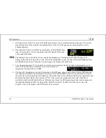
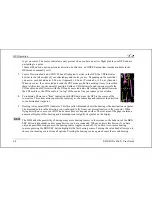
change to the NAV radio, just like a mechanical HSI or CDI does. In the case of the SL-30, either the OBS
knob on the SL-30 or the HS34 may be used.
3.
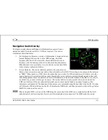
Course Deviation Indicator (CDI). When tuned to a VOR, the CDI indicates how far to the
left or right of your selected radial you are. Full scale deviation indicates ten degrees of
deviation from the radial that has been chosen as the course. When tuned to a localizer, full
scale represents 2.5 degrees of deviation. When on course, the course indicator and the CDI
make a solid line, making it easy to see when there is little error in your aircraft's position.
Unlike a CDI indicator found in basic aircraft, the CDI needle on an HSI rotates with the DG
and course indicator. By turning the aircraft towards the CDI needle you reduce your deviation.
4.
To/From indicator. Because an HSI rotates the course line on top of the DG, the to/from indicator
always points TO the physical VOR or localizer transmitter. If it is pointing the same way as the
course line, then that is a "to" indication. If it's pointing away from the course line, then that is a
"from" indication. This data comes from the to/from flag indicator.
5.
Glideslope Indicator. This appears only when tuned to an ILS. It displays deviation as 0.5 degrees
when deflected full scale. This does not have an indicator on it unless the glideslope is valid as defined
by the glideslope flag.
6.
Glideslope flag. This appears when the radio is tuned to a localizer and the glideslope is
not valid. When this is active, there is no indicator mark on the GS scale.
to
e
7.
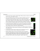
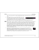
Bearing To indicators. These arrows show you the bearing to the active and standby
VORs. This is the direction that you would need to fly to go directly from where you are
the transmitter. When flying directly on course, your bearing and course lines overlap on
another. The primary bearing indicator is depicted by a yellow diamond and the standby
indicator is depicted by an orange circle. These elements only appear when the active
and/or standby VORs are tuned to an active frequency. A numerical display of your
Summary of Contents for EFIS-D10A
Page 2: ......
Page 8: ...Table of Contents viii EFIS D10A Pilot s User Guide Appendix D EFIS D10A Specifications 8 8...
Page 34: ......
Page 60: ......

