background image


Appendix 

EFIS-D10A Pilot’s User Guide 

7-3 

1.


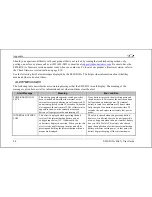
Each numeric value and gauge posts its alarm by turning red, blinking, bringing up the alarm bar, and triggering the 
external light and audio alert. 

2.


Alarm messages in the alarm bar are stacked into memory and presented in the order in which they occurred, unless 
a higher priority alarm occurs. Removal of the Alarm Bar requires separate pilot acknowledgement of each alarm. 

3.


The ACK button displays a number indicating the number of stacked up alarms. 

4.


When the last alarm is acknowledged, the Alarm Bar and Alarm Menu are removed from the screen. 

5.


Once the top alarm is acknowledged, the next alarm in the stack is shown. 

DSAB Alerts 


When multiple Dynon Avionics instruments are networked together via DSAB, there are a few error messages 
designed to warn you of failures or reduced functionality. 

NETWORK CONFIGURATION ERROR

: This error can only occur within a short period of time after the system is 

turned on. This error indicates that a unit that was expected to be on the DSAB network was not found. For example, if – 
in a system consisting of a FlightDEK-D180, EFIS-D100, and an HS34 – all three units are not present, this error 
appears. This error is displayed when any part of the system is not working, including backup EDCs or OATs. 

If this error is unexpected, check all Dynon equipment for proper function, and cycle the power to all units. Additional 
information on the missing unit can be found on the network status page under SETUP > DSAB > STATUS. If a unit is 
purposefully removed from the system, refer to the EFIS-D10A Installation Guide for instructions on reconfiguring the 
network. 

NETWORK CONNECTION LOST

: This error means that all network communication has stopped. In this event, no 

instruments share data or settings until the cause of the communication problem is resolved and all units are power 
cycled. Individual units that are powered on and functioning continue to function using their internally-derived data. 

Summary of Contents for EFIS-D10A

Page 1: ...tem Pilot s User Guide Revision F For use with firmware version 4 0 0 September 10 2007 Dynon Avionics This product is intended for the experimental and Light Sport aircraft categories and is not appr...

Page 2: ......

Page 3: ...storage medium to be viewed for personal use provided that such electronic or printed copy of this manual or revision must contain the complete text of this copyright notice and provided further that...

Page 4: ...HETHER RESULTING FROM THE USE MISUSE OR INABILITY TO USE THIS PRODUCT OR FROM DEFECTS IN THE PRODUCT SOME STATES DO NOT ALLOW THE EXCLUSION OF INCIDENTAL OR CONSEQUENTIAL DAMAGES SO THE ABOVE LIMITATI...

Page 5: ...arning 1 2 About this Guide 1 2 2 Product Overview 2 1 EFIS D10A Hardware 2 1 Power 2 1 Sensors and Inputs 2 2 Dynon Smart Avionics Bus 2 2 Outputs 2 2 Display 2 3 Buttons and Knobs 2 3 Theory of Oper...

Page 6: ...4 2 HSI Page 4 9 Times Auxiliary Page 4 9 Lists Pages 4 10 Menu Pages 4 11 5 EFIS Operation 5 1 POWER Power on off 5 1 BARO Setting Barometer Altitude 5 1 BUGS Setting Bug Markers 5 2 Heading 5 2 Airs...

Page 7: ...6 1 Accessing the HSI DG Page 6 2 HSI Display Basics 6 2 Navigation Radio Overlay 6 5 GPS Overlay 6 7 HSI Menu Structure 6 10 7 Alerts 7 1 Alarm Indicators 7 1 Show Page 7 2 Alarm Acknowledgement 7 2...

Page 8: ...Table of Contents viii EFIS D10A Pilot s User Guide Appendix D EFIS D10A Specifications 8 8...

Page 9: ...ded in flight CAUTION in a flying situation it is the pilot s responsibility to use the product and the guide prudently OEM Installations EFIS D10A Pilot s User Guide 1 1 If your EFIS D10A is installe...

Page 10: ...configure and get acquainted with the EFIS D10A s many functions The second is to give you quick access to vital information For detailed technical and installation information please refer to the EFI...

Page 11: ...Guide 2 1 The EFIS D10A can be ordered with an optional internal battery which allows the instrument to continue to operate in the event of an external power failure This lithium ion battery is recha...

Page 12: ...ct s data can then be viewed on any other screen in the DSAB network For example an EFIS has the ability to display engine monitor information if it is connected to an EMS or FlightDEK D180 Note that...

Page 13: ...ctive parameters on the HSI page Theory of Operation The primary flight instruments on your EFIS display are generated using a group of calibrated sensors All of them are solid state that is there are...

Page 14: ...S D10A depends on airspeed pitot and static for most of the other AHRS indicators If a problem develops with your airspeed reading treat all of the instruments on your EFIS with skepticism especially...

Page 15: ...ins buttons and a display Buttons There are six buttons on the front panel of the EFIS D10A Throughout this guide these buttons are referred to as one through six with button one being the leftmost an...

Page 16: ...in this section and are defined as follows Screen Screen Configuration Screens consist of one or two pages from the EFIS D10A or from another DSAB connected Dynon Avionics product Page A page is a sec...

Page 17: ...presented by one of two icons on D10 series product The table at right shows the two icons and their meaning The predefined screen configurations with their respective icons are as follows EMS TIMES A...

Page 18: ...stay on the same screen you may either select your currently displayed screen with the caret and press GOTO or press CANCEL Screen Cycling Using Hotkeys With no menu displayed press button one to cycl...

Page 19: ...the boot screen Next press the TOGGL button on any selected screen to toggle the icon All screens that show the icon are included in the rotation Any screen in the rotation may be accessed via the but...

Page 20: ...page and pressing buttons four or five below the right 1 2 of the screen displays the main menu for the right page see the figure to the right FUNCTIONALITY A menu consists of two rows of gray boxes c...

Page 21: ...tton labels for MENU BARO BUGS LISTS MORE and EXIT Pressing MORE reveals the rest of the EFIS menu This menu contains options for SETUP INFO DIM TIMER MORE and EXIT Pressing MORE on this menu simply r...

Page 22: ...is varies based upon how deep you are into the menu system DESCRIPTIONS IN THIS GUIDE Throughout this guide the character is used to indicate entering a deeper level of the menu system For example EFI...

Page 23: ...rce external to the EFIS D10A Refer to the EFIS D10A Installation Manual for a list of compatible equipment EFIS D10A Pilot s User Guide 4 1 Note EMS based pages use data that is obtained from Dynon s...

Page 24: ...yed items described below may not be onscreen depending on whether or not they have been enabled in the CLUTTR menu Beginning with firmware revision 3 0 Dynon adopted a dramatically different EFIS dis...

Page 25: ...has an internal arrow which moves to stay perpendicular to the horizon The moving roll indicator type 2 rotates the scale about a stationary internal arrow which points to the current roll angle on t...

Page 26: ...ading while the surrounding ta scrolls beneath its arrow You may set a yellow bug on this tape as a heading reminder The pointer in the digital read is hollow to allow the GPS ground track indicator d...

Page 27: ...w The digital readout s digits scroll up and down simulating an analog altimeter and giving a sense of the direction of movement Thousands of feet are displayed using large numbers while hundreds of f...

Page 28: ...Probe displays the aircraft s current AOA relative to the stall AOA The AOA calibration process should result in the lowest angle of attack stall usually the clean configuration occurring between the...

Page 29: ...rspeed color thresholds via the SETUP menu Refer to the EFIS D10A Installation Guide for more information on setting the airspeed color thresholds The airspeed trend indicator is located to the left o...

Page 30: ...of Mercury or millibars depending on your preference set in the EFIS BARO menu Clock timer The clock is displayed in the lower left hand corner of the screen below the airspeed tape To set the clock e...

Page 31: ...y additional navigation information For detailed information on using the HSI page please see the HSI Operation section on page 6 1 Times Auxiliary Page Available in 1 2 1 2 format This page displays...

Page 32: ...s user defined checklists and data panels to be used for waypoint information lists of radio frequencies or other informational purposes You may define up to twenty five lists Each checklist data pane...

Page 33: ...ed line Use the DOWN and UP buttons to scroll through the list of options Any line on a Menu Page that is followed by has more options to configure inside of it Press SEL to expand the menu into anoth...

Page 34: ......

Page 35: ...is still connected the unit is never fully turned off It simply enters an extremely low power state allowing it to keep track of time It is acceptable to have the EFIS D10A on during engine crank It i...

Page 36: ...exactly enough to preserve that saved value This is not a replacement for setting the barometer by the pilot before takeoff it makes the barometer very close to the correct value minimizing the amount...

Page 37: ...f rotating the HEADING knob causes the bug to be displayed on the heading tape To sync the bug your current heading press the heading to knob briefly To toggle the heading bug on or off push and hold...

Page 38: ...ge the bug s set value Toggling the altitude bug on activates the altitude alerter function with the bug value as the target altitude While climbing or descending toward the target altitude a level of...

Page 39: ...be included beneath 5 user configurable categories and each category can contain up to 5 checklists or data panels By default the EFIS D10A is loaded with the following 5 categories CHKLIST RADIO POH...

Page 40: ...network unit preferences are shared between all connected instruments SET THE CLOCK Entering the EFIS SETUP CLOCK menu displays the local and Zulu times in the value setting box Because local time is...

Page 41: ...t of tips as you set the clock Set both the local and Zulu times in military time You have may display the time in either military or standard 12 hour format as described below SEL moves the highlight...

Page 42: ...of the graphical airspeed tape IASDIG Indicated Airspeed Digital Toggles the display of the digital airspeed window HDG Heading Toggles the display of the heading tape and digital display BALL Slip sk...

Page 43: ...ayed the EFIS D10A cannot detect your GPS or the GPS does not yet have a satellite lock WIND Winds Aloft Toggles the display of the wind arrow and speed indicator The display of winds aloft requires a...

Page 44: ...g tape Like the CDI this can only be displayed when the EFIS D10A is receiving a valid course from the nav source selected on the HSI page If the CRS button status displays Y and no course pointer is...

Page 45: ...leration experienced by the EFIS D10A measured in g s where 1 g is the amount of acceleration due to the earth s field experienced by an object at sea level Positive g force is defined as upward verti...

Page 46: ...calculator without an OAT installed manually enter the outside air temperature in the EFIS OATSET menu When a temperature is manually input via the OATSET menu a box is displayed around the temperatu...

Page 47: ...which can be used to automatically dim all of the screens connected to a DSAB network To turn this function on press AUTODIM When you enable auto dim the screen does not immediately change brightness...

Page 48: ...g or configuring the timer on one instrument causes all other instruments to reflect the change OATSET Setting Temperature Offset If you did not purchase an EFIS or EMS outside air temperature sensor...

Page 49: ...culations and displays are done in reference to the local magnetic heading The HS34 supports a variety of connections to navigation receivers via serial ARINC 429 and analog connection A connection to...

Page 50: ...all times Changing the source of information on one HSI page affects all units as does changing scaling bugs or bearing pointers It is not possible to show a NAV radio on one screen and a GPS on anoth...

Page 51: ...the radio is tuned to a localizer The glideslope scale is visible as well but may be flagged invalid e BC in yellow text This indication means that the radio is tuned to a localizer and is in back co...

Page 52: ...of the bug 5 True Airspeed Indicator If it is possible to calculate true airspeed on the device then it is displayed here In order to do this the device must have access to an outside air temperature...

Page 53: ...S When tuned to a VOR this is the radial that you wish to fly When tuned to an ILS this is set to the runway heading In a situation with no winds keeping the course indicator pointed straight up and i...

Page 54: ...e physical VOR or localizer transmitter If it is pointing the same way as the course line then that is a to indication If it s pointing away from the course line then that is a from indication This da...

Page 55: ...adjusting anything or pressing any buttons the selection self clears GPS Overlay The figure at right shows an HSI page with information sourced from a GPS receiver while the GPS has an active flight p...

Page 56: ...4 To indicator There is no from indication with GPS data since the GPS is the source of the course line This arrow always points the same way as the course line and indicates the direction to the des...

Page 57: ...match the mode and range of the GPS at all times When in this mode the range is not limited to just 5 1 0 3nm as the GPS may slide between scales so it would not be unexpected to see a number such as...

Page 58: ...well as the EFIS heading tape The heading bug can be adjusted at any time by rotating the HS34 s HEADING knob If the bug is currently toggled off rotating the HEADING knob causes the bug to be display...

Page 59: ...tion EFIS D10A Pilot s User Guide 6 11 SCALE GPS mode This is used to cycle through the three GPS scale modes The scale button only exists if the source you are connected to is not providing scale inf...

Page 60: ......
Page 61: ...condition the EFIS D10A does not alert you audibly The audio out connection on the EFIS D10A is for AOA alerts only If you have a Dynon EMS based product installed connected to both your EFIS D10A and...

Page 62: ...umber next to it indicating the number of currently posted alarms If this number is higher than 1 after you press ACK you will see the alarm text for the next posted alarm Pressing ACK does the follow...

Page 63: ...only occur within a short period of time after the system is turned on This error indicates that a unit that was expected to be on the DSAB network was not found For example if in a system consisting...

Page 64: ...ed by THIS or DSAB on each connected display instrument If the label is THIS then the screen with this label is the source of the failure If the message begins with DSAB than the message indicates a f...

Page 65: ...onnection to these serial ports can be found in the EFIS D10A Installation Guide To log EFIS data you must connect the serial port to a PC This serial data can be logged using any standard serial term...

Page 66: ...in 1 10 degrees 1800 180o 18 3 Yaw 000 to 359 in degrees 000 North 090 East 180 South 270 West 21 4 Airspeed 0000 to 9999 airspeed in units of 1 10 m s 1555 155 5 m s 25 1 Altitude Sign or positive me...

Page 67: ...d VSI is output in characters 30 33 48 2 Internal use Internal use ignore 50 2 Checksum The ascii hex 2 byte sum of all 49 preceding bytes 52 2 CR LF Carriage Return Linefeed 0x0D 0x0A As an example t...

Page 68: ...connected If no button is pressed within 30 seconds of when the alert appears the unit turns off The voltmeter also appears to show you the currently measured battery voltages prior to the unit turnin...

Page 69: ...normal operation TEMPERATURE OUT OF SPEC This alert appears when the ambient temperature sensed by the unit is below 30 C or above 50 C The sensors in the unit have a certain temperature range within...

Page 70: ...rmware in your EFIS D10A while the remote compass was not connected If this is the case try uploading the new firmware again with the EDC D10A connected Attempt the connection within the first few sec...

Page 71: ...NIT This error can occur for a few reasons including an aborted upload When this error appears it may be possible to recover your unit in the field The best way of ensuring this is to call Dynon Avion...

Page 72: ...ith internal battery Operating Temperature 22 to 122 F 30 to 50 C Power Voltage 10 30 Vdc Power 8 watts typical 13 watts maximum Connections Wiring D 25 male Screen Type AMLCD TFT Thin Film Transistor...

Reviews: