background image


SkyView 

HDX System


General Maintenance Manual, Revision F 

Page | 17 


4  Functional Description and Operation 

This  section  provides  an  overview  of  the  major  functions  and  operation  of  a  SkyView  HDX 
System. 

4.1 

SkyView HDX Displays 

SkyView  HDX  displays  are  multi-functional,  high-definition,  LCD  color  displays  that  present 
integrated  Primary  Flight  Information  (PFI),  NAV/GPS  information,  Moving  Map,  COM  radio 
information  and  control,  Transponder  information  and  control,  ADS-B  IN  and  OUT,  Engine 
Monitoring, and Autopilot information and control. 

SkyView HDX displays are available in two sizes: 

  the SV-HDX1100 is a 10.1-inch, 1280 x 800-pixel display, 

  the SV-HDX800 is a 7.1-inch, 1280 x 800-pixel display. 

The  displays  utilize  backlighting  technology  for  increased  lifespan,  more  uniform  brightness, 
superior dimmability, and reduced power consumption. Up to three SkyView HDX  displays, in 
any combination of the two sizes, can be installed in the airpla

ne’s instrument panels. 

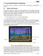
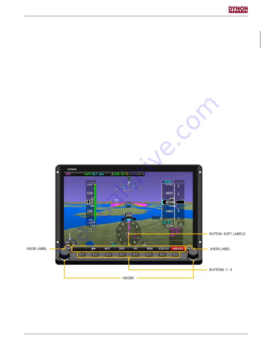
Figure 4

 shows the front of a 10" display (SV-HDX1100) and its important parts. (The figure is 

also applicable for the SV-HDX800.) 


Figure 4: SkyView HDX Display (SV-HDX1100 shown) 

The structure surrounding the lighted LCD screen is referred to as the bezel. All tactile controls 
for the system are located on the tilted shelf at the bottom of the bezel. Buttons, knobs, and an 
integrated light sensor are located on the bezel. User interaction takes place via two knobs with 
integrated buttons, eight buttons along the bottom of the bezel, and via  tactile pressing on the 
screen itself. The light sensor is used for automatic screen brightness control. 

Summary of Contents for SkyView HDX Series

Page 1: ...eral Maintenance Manual includes Instructions for Continued Airworthiness 103221 000 Revision F 12 18 2019 Copyright 2019 by Dynon Avionics Inc Dynon Avionics grants third parties permission to print...

Page 2: ...download a single copy of this manual and of any revision to this manual onto a hard drive or other electronic storage medium to be viewed for personal use provided that such electronic or printed cop...

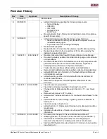
Page 3: ...ormation to System Description Troubleshooting sections verified edited and standardized Removal and Installation sections verified edited and standardized Added EMS Sensors information to Troubleshoo...

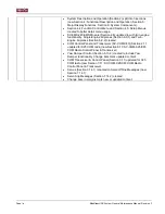
Page 4: ...anes Section 6 9 1 and Twin Engine Airplanes Section 6 9 2 created COM Control Panel and Transceiver SV COM X83 Section 2 11 updated for X25 COM radio now Section 6 10 SV COM X25 X83 COM Radio Control...

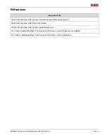
Page 5: ...iew HDX System Cert Aircraft Flight Manual Supplement 102949 003 SkyView HDX Pilot s User Guide 1 103261 000 SkyView HDX System Installation Manual 43 13 1B Acceptable Methods Techniques and Practices...

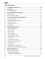
Page 6: ...ol Menu 21 4 5 Setup Menus 23 5 Major Display Functions 25 5 1 Primary Flight Display 25 5 2 Attitude Indicator 26 5 3 Altitude Indicator 27 5 4 Airspeed Indicator 28 5 5 Vertical Airspeed Indicator 2...

Page 7: ...eshooting 58 7 1 Identifying Failures 58 7 2 SV HDX1100 SV HDX800 Displays 60 7 3 SV ADAHRS 200 ADAHRS Module 61 7 4 SV MAG 236 Remote Magnetometer 64 7 5 SV GPS 2020 GPS Antenna Receiver 64 7 6 SV BA...

Page 8: ...V COM PANEL COM Radio Control Panel 105 8 18 SV ARINC 429 ARINC 429 Connection Module 106 8 19 AoA Probe 107 8 20 Autopilot Servos 108 8 21 SV AP PANEL Autopilot Control Panel 109 8 22 SV BUTTON LEVEL...

Page 9: ...SkyView HDX System General Maintenance Manual Revision F Page ix 9 9 Transponder Tests 122 9 10 Compass Calibration 123 10 Appendix 1 Glossary 127...

Page 10: ...endix G G23 4 that result from this modification The Airworthiness Limitations Section is FAA approved and specifies maintenance required under 14 CFR 43 16 and 91 403 of the Federal Aviation Regulati...

Page 11: ...val and installation of Skyview HDX system components Service Provides information and instructions for the continued airworthiness of the Skyview HDX system and components 2 1 1 Document Control This...

Page 12: ...fail Air data and airplane motion information is collected by the Air Data Attitude Heading Reference System ADAHRS module Engine fuel and electrical system information is collected by the EMS module...

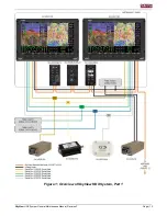
Page 13: ...SkyView HDX System General Maintenance Manual Revision F Page 13 Figure 1 Overview of SkyView HDX System Part 1...

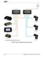
Page 14: ...Page 14 SkyView HDX System General Maintenance Manual Revision F Figure 2 Overview of SkyView HDX System Part 2...

Page 15: ...ator Horizontal Situation Indicator Inclinometer Vertical Speed Indicator Outside Air Temperature True Airspeed Density Altitude Ground Speed Wind Velocity Indicator Flight Path Indicator Synthetic Vi...

Page 16: ...he SkyView HDX system the EFIS D10A see Figure 3 serves as a backup Altitude Attitude and Airspeed indicator in the event of a SkyView HDX Display failure or loss of power The flight instruments on EF...

Page 17: ...splays utilize backlighting technology for increased lifespan more uniform brightness superior dimmability and reduced power consumption Up to three SkyView HDX displays in any combination of the two...

Page 18: ...e the system is fully powered on It presents knob and button labels in a menu arrangement Knob and button functionality are contextually based and determined by what is presented on the screen The lab...

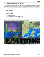
Page 19: ...nfigured to present Optional Content Secondary displays can be configured to present any type of information Primary Content PFD Optional Content Moving Map display Engine Monitoring System EMS displa...

Page 20: ...pages the pilotselects A button has a function if a label displays above it If there is no label then no function is available Some buttons have additional behavior when the button is pressed and held...

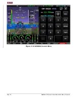
Page 21: ...Button 7 The icons in MENU are tactile and touching them opens the Control Page for the function For example touching the COM RADIO icon opens its Control Page see Figure 9 There are also shortcut ic...

Page 22: ...Page 22 SkyView HDX System General Maintenance Manual Revision F Figure 9 COM RADIO Control Menu...

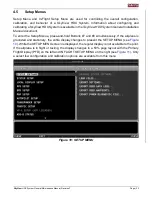
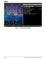
Page 23: ...To enter the Setup Menus press and hold Buttons 7 and 8 simultaneously If the airplane is grounded and stationary the entire display changes to present the SETUP MENU see Figure 10 While the SETUP ME...

Page 24: ...Page 24 SkyView HDX System General Maintenance Manual Revision F Figure 11 IN FLIGHT SETUP MENU...

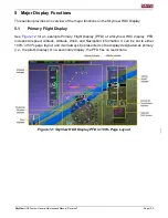
Page 25: ...ay See Figure 12 for an example Primary Flight Display PFD of a SkyView HDX display PFD includes Airspeed Altitude Attitude Wind and Navigation information It can be set to either 100 or 50 page layou...

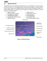
Page 26: ...a from the ADAHRS module is used to present the Attitude Indicator on a SkyView HDX display The Attitude Indicator includes the following sub indicators symbols markers and reference scales Slip Skid...

Page 27: ...f the airplane The pilot can set an altitude bug using a knob The bug appears on top of numerically and inside graphically the indicator The pilot can also set barometric pressure BARO using a knob Ba...

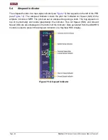
Page 28: ...shows the pilot the Indicated Air Speed IAS of the airplane in knots or MPH The pilot can set an airspeed bug using a knob The bug appears on top of numerically and inside graphically the indicator T...

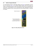
Page 29: ...PFD see Figure 12 The Vertical Airspeed Indicator tells the pilot whether the airplane is climbing descending in FPM or level in flight The pilot can set a vertical speed bug using a knob The bug appe...

Page 30: ...bug is the Cyan colored indicator that appears on inside graphically of the Compass Rose indicator Data from the ADAHRS module Remote Magnetometer GPS Antenna Receiver and NAV devices are used to pre...

Page 31: ...the right side of the PFD just below the Vertical Speed Indicator see Figure 12 Data from the ADAHRS module or Remote Magnetometer via the OAT sensor are used to present the OAT Indicator and Density...

Page 32: ...atabase and the proximity of the aircraft to terrain The synthetic vision advisory is based both on altitude and on flight path Terrain shown in Red is an immediate threat to the airplane The map advi...

Page 33: ...on see Figure 19 and Flight Planning see Figure 20 functions The Moving Map has touchscreen functionality and can present airport airspace obstacles and other available aviation data The Moving Map is...

Page 34: ...Page 34 SkyView HDX System General Maintenance Manual Revision F Figure 19 Navigation Info in Split Screen 50 Layout Figure 20 Flight Plan in Split Screen 50 Layout...

Page 35: ...Installation Manual document for information about loading charts 5 12 2 GPS Sources To present the Moving Map and Navigation and Flight Planning functions a SkyView HDX display needs to be connected...

Page 36: ...Notification Area Showing a Warning Notification Whenever a new alert or message is generated the message notification indicator also the soft key label will flash to provide a visual indication that...

Page 37: ...inoperative See Section 7 2 3 BACKUP BATTERY LOW The backup battery connected to this display is low See Section 7 6 ADAHRS FAIL ADAHRS failure See Section 7 3 EMS FAIL Engine monitor failure See Sect...

Page 38: ...on is not available GPS is being used to aid in the computation of attitude information Attitude may be degraded HDG SOURCE FAIL The Remote Magnetometer has failed or is no longer communicating via Sk...

Page 39: ...2 months or more has passed since the last successful backup battery test or the last three SkyView HDX Display shutdowns were abnormal See Section 9 4 B U BATT LOW CHARGE The backup battery connected...

Page 40: ...if Autopilot servos are not receiving power See Section 7 14 1 SYSTEM EVENT X SkyView HDX has detected a possible problem with software or hardware Contact Dynon technical support Always have a prope...

Page 41: ...backup battery that provides power for at least 45 minutes The EFIS D10A flange mounts to an instrument panel Figure 23 EFIS D10A 6 2 SV BAT 320 Backup Battery If avionics power is lost in flight a pr...

Page 42: ...axes pressure transducers for measuring air data and magnetometers on all three axes for measuring magnetic heading Pitot Static and AoA lines are connected to an SV ADAHRS 200 module An OAT sensor ca...

Page 43: ...A Internal Magneto meter Remote Magneto meter Rate Sensors Accelero meter OAT Heading HDG Remote Magnetometer Heading HDG Magnetometer Fail Synthetic Vision Internal Magnetometer Synthetic Vision Remo...

Page 44: ...ould be installed in an area free of magnetic disturbances while remaining within proximity of the airplane s center of gravity An OAT sensor can be connected to an SV MAG 236 Figure 26 SV MAG 236 6 5...

Page 45: ...DX display and it will continue to provide position updates when the SkyView HDX display is operating on backup battery power An SV GPS 2020 provides high integrity GPS position and time data to a Sky...

Page 46: ...n Class B or Class C airspaces Up two SV XPNDR 261 transponders can be installed in a SkyView HDX System Figure 29 SV XPNDR 261 6 8 SV ADSB 472 ADS B IN Receiver The SV ADSB 472 see Figure 30 is a dua...

Page 47: ...perature EGT Turbine Inlet Temperature TIT Fuel Pressure Fuel Flow Fuel Level Flap Position Landing Gear Position Pitot Heat SkyView HDX can monitor more than one engine provided a dedicated EMS modul...

Page 48: ...formation on the SkyView HDX Display The Bottom Band provides the ability to keep the engine display visible along with other required flight information all on one screen Generic configuration files...

Page 49: ...ion always be displayed to the pilot Loading the EMS configuration file for your airplane is required to configure the system for dual EMS modules and the dedicated EMS display This file will also inc...

Page 50: ...Page 50 SkyView HDX System General Maintenance Manual Revision F Figure 35 Typical Twin Engine EMS Presentation in 50 Page Layout Figure 36 Typical Twin Engine EMS Presentation in Bottom Bar...

Page 51: ...is available in horizontal and vertical orientations The SV COM X25 operates at 118 000 MHz to 136 992 MHz with 25 kHz channel spacing The SV COM X83 operates at 118 000 MHz to 136 992 MHz with confi...

Page 52: ...ble in horizontal and vertically orientations to accommodate various instrument panel layouts Operationally the two versions are identical Without the Knob Control Panel ALT BARO and HDG TRK bugs are...

Page 53: ...on when coupled to an external navigation source In addition the autopilot can have a third servo connected to the rudder The rudder servo acts as a yaw damper to reduce and prevent yaw excursions whi...

Page 54: ...current GPS ground track if OBS is not set ALT Holds altitude commanded in the Autopilot status bar When activating this mode commanded altitude is automatically set to the current indicated altitude...

Page 55: ...selector will turn green when engaged The Slip Skid indicator will also appear green with the letters YD in black when the Yaw Damper is turned ON and white when the Yaw Damper is turned OFF as shown...

Page 56: ...s an Autopilot Disconnect A P DISC button for SkyView HDX Systems with Autopilot An A P DISC button is required on SkyView HDX Systems with Autopilot The button can be mounted on the instrument panel...

Page 57: ...llations The SV NET HUB simplifies component connection to the SkyView HDX Network Figure 46 SV NET HUB 6 15 Panel Mount USB Port The Panel Mount USB Port see Figure 47 is an optional accessory that i...

Page 58: ...AHRS module fails see Figure 48 If an EMS module fails there will be a Red X over the entire EMS display segment bottom band 50 page etc and a yellow EMS FAIL label see Figure 50 If a sensor fails onl...

Page 59: ...SkyView HDX System General Maintenance Manual Revision F Page 59 Figure 49 Example of a GPS Antenna Receiver Failure Figure 50 Example of an EMS Module Failure...

Page 60: ...eps a Access rear of SkyView HDX Display see Section 8 4 1 b Observe the lights on the ethernet port Unlike other ethernet ports these lights are used for display status Yellow light ON Power is conne...

Page 61: ...w HDX Display see Section 8 4 1 Test all wiring leads and make sure wiring is correct per SkyView HDX Wiring Diagram document 7 3 SV ADAHRS 200 ADAHRS Module 7 3 1 Red X Over Primary Flight Display Th...

Page 62: ...atic sensor 4 Make sure air flows readily through tube lines and out Static sensor 5 Re connect Static tube to ADAHRS Static connection 6 Test the system to ensure proper functionality 7 3 4 Density A...

Page 63: ...es then there may be a problem with the pneumatic tube from the AoA probe to the ADAHRS module 2 Check for blockage or disconnection of AoA probe tubing a Remove AoA probe and make sure the pneumatic...

Page 64: ...the SkyView HDX Display To check the connection complete the following 1 Access rear of SkyView HDX Display see Section 8 8 and check fix wiring connections 2 If wiring appears correct and GPS is sti...

Page 65: ...fast rate This fast change in temperature can sometimes reduce the reliability of the output of the sensors Therefore this alert is displayed and the horizon indication is changed from blue brown to g...

Page 66: ...sor Failures The following list represents the sensors that may be installed on your airplane Oil Pressure Oil Temperature Fuel Pressure Fuel Flow Fuel Level Manifold Air Pressure MAP Carburetor Tempe...

Page 67: ...ernal diagnostic warning Internal fault contact Dynon technical support to arrange for repair or replacement REMOTE HOT value Transponder is receiving excessive heat value is Temperature C Check locat...

Page 68: ...arness for proper connections between COM Control Panel and COM Transceiver modules 3 Check rear of COM Control panel A red LED indicator on rear of module confirms hardware operation a Red light OFF...

Page 69: ...the airplane approaches a stall If no AoA audio alerts are heard approaching a stall perform the following checks 1 Verify audio is heard for other SkyView HDX system messages If audio is heard for ot...

Page 70: ...in YELLOW a software upgrade did not complete properly 6 If all above fails contact Dynon technical support Always have a properly rated mechanic or qualified facility remove unit 7 14 2 Servo Slip M...

Page 71: ...ilot Level Button 1 Check if SkyView HDX Display has generated an error messages associated with button 2 If there are no error messages associated with button engage Autopilot by pressing LEVEL butto...

Page 72: ...SkyView HDX network but is getting power c Red light ON flashing quickly The control panel is connected to SkyView HDX network and is communicating properly d Red light ON not flashing The control pa...

Page 73: ...t installed the SkyView HDX system That document should be kept with the airplane 8 2 Access to Equipment See Figure 52 and Figure 53 for typical SkyView HDX system components locations and layouts Th...

Page 74: ...Page 74 SkyView HDX System General Maintenance Manual Revision F Figure 52 Typical Instrument Panel Front View landscape view...

Page 75: ...SkyView HDX System General Maintenance Manual Revision F Page 75 Figure 53 Typical Instrument Panel Rear View landscape view...

Page 76: ...Page 76 SkyView HDX System General Maintenance Manual Revision F Figure 54 HDX1100 Avionics Tray...

Page 77: ...SkyView HDX System General Maintenance Manual Revision F Page 77 Figure 55 HDX800 Avionics Tray...

Page 78: ...Page 78 SkyView HDX System General Maintenance Manual Revision F Figure 56 Remote Module Mounting Tray...

Page 79: ...trol Panel 6 SV KNOB Panel Knob Control Panel 7 SV BUTTON APDISC Autopilot Disconnect Button 8 SV ARINC 429 ARINC 429 Interface Module 9 SV ADAHRS 200 ADAHRS 10 SV EMS 220 Engine Monitoring System 11...

Page 80: ...2 OR USE COMPARABLE SV EMS 220 AN526 832 XX PHILLIPS TRUSS HEAD STAINLESS MACHINE SCREW 8 32 OR USE COMPARABLE SV COM T25 T8 AN526 832 XX PHILLIPS TRUSS HEAD STAINLESS MACHINE SCREW 8 32 OR USE COMPAR...

Page 81: ...TTN STL 6 32 5 8IN BLK ZINC PURCHASE KIT 102487 000 SALE ASSY KIT SCREWS PANEL MOUNT SV KNOB PANEL 101281 007 SCREW 5 64IN HEX BTTN STL 6 32 5 8IN BLK ZINC PURCHASE KIT 102487 000 SALE ASSY KIT SCREWS...

Page 82: ...Manual Revision F 8 4 SV HDX1100 SV HDX800 Displays This section provides removal and installation procedures for the primary and secondary SkyView HDX Displays Figure 57 SV HDX110 or SV HDX800 Front...

Page 83: ...d gain access to connectors 4 Disconnect all cables and D37 and D9 electrical connectors from back of unit This is accomplished by removing two retention screws on both D37 and D9 electrical connector...

Page 84: ...ionics tray For specific location see the Equipment Installation Record document associated with the airplane 8 5 2 Removal 1 Shut down airplane power 2 Disconnect pitot static and AoA if installed pn...

Page 85: ...ee Section 8 18 3 5 If original ADAHRS module is re installed perform a pitot static leakage test see Section 9 6 6 If new ADAHRS unit is installed perform SkyView Network Configuration pitot static l...

Page 86: ...e You may need to de pin connector from wiring to remove Keep nylon nut and washer for re installation 8 6 3 Installation 1 Install OAT sensor in same location using nylon nut and washer see Table 11...

Page 87: ...lation procedures for the Remote Magnetometer unit Figure 61 SV MAG 236 8 7 1 Location For specific location see the Equipment Installation Record document associated with the airplane 8 7 2 Removal 1...

Page 88: ...see Section 9 10 8 8 SV GPS 2020 GPS Antenna Receiver This section provides removal and installation procedures for the Global Positioning System GPS Antenna Receiver Figure 62 SV GPS 2020 8 8 1 Loca...

Page 89: ...tenna Receiver wiring connector to SkyView HDX wiring harness You may need to re pin connector to wiring 3 Restore power to airplane 4 Turn SkyView system ON 5 With airplane unobstructed from sky veri...

Page 90: ...ent Installation Record document associated with the airplane 8 10 2 Removal 1 Shut down airplane power 2 Remove nuts from mounting studs see Figure 64 that secure EFIS D10A to instrument panel and th...

Page 91: ...Phillips or D sub screws To access rear of EFIS D10A it may need to be removed from instrument panel see Section 8 10 2 If access permits EFIS D10A may remain in instrument panel Not removing pitot a...

Page 92: ...re 65 SV EMS 220 8 12 1 Location On single engine airplanes tThe EMS module is typically commonly located behind the SkyView HDX display on the avionics tray On twin engine airplanes the common locati...

Page 93: ...led location information Removal To remove the oil pressure sensor follow the removal instructions in the airplane or engine manufacturer s maintenance manuals Installation To install the oil pressure...

Page 94: ...sensor is normally located in the fuel plumbing downstream of the fuel metering device if fuel injected and upstream if carbureted Refer to the airplane or engine manufacturer s maintenance manuals f...

Page 95: ...Using a wrench unthread sensor from its threaded mounting boss 3 Remove sensor from boss 4 If sensor is not immediately replaced temporarily cover open boss to prevent system contamination Installatio...

Page 96: ...e the following steps 1 Loosen attachment clamp completely 2 Remove sensor from hole in exhaust stack Installation To install an EGT sensor follow the installation instructions in the airplane or engi...

Page 97: ...wire connected to output side of sensor 7 Remove screws that secure sensor to airframe and then remove sensor Installation To install the Amp sensor follow the installation instructions in the airplan...

Page 98: ...e equipped with this sensor refer to the SkyView HDX System Equipment Installation Record document to see where the sensor is located on your airplane Removal To remove the MAP sensor follow the remov...

Page 99: ...ow the installation instructions in the airplane or engine manufacturer s maintenance manuals 8 12 18 Landing Gear Position Sensor The SV EMS 220 utilizes the Landing Gear position sensing switches or...

Page 100: ...ovides removal and installation procedures for the Transponder module Figure 66 SV XPNDR 261 8 13 1 Location Typically the Transponder module is located as close to its antenna as possible For specifi...

Page 101: ...it from airplane 8 13 3 Installation 1 Install Transponder module into tray and secure with retaining clip 2 Connect D25 connector and antenna TNC connector to Transponder module 3 Restore power to a...

Page 102: ...to see any ADS B ground stations The status line can display any of the following states NOT FOUND The device is not communicating with SkyView HDX This usually means a connectivity wiring problem bet...

Page 103: ...ation The ADS B Antenna is typically located on the underside of the airplane For specific location see the Equipment Installation Record document associated with the airplane 8 15 2 Removal 1 Shut do...

Page 104: ...ansceiver Figure 69 SV COM T25 and SV COM T8 8 16 1 Location For specific location see the Equipment Installation Record document associated with the airplane 8 16 2 Removal 1 Shut down airplane power...

Page 105: ...h the COM system If there is an error message see Section 7 11 8 17 SV COM PANEL COM Radio Control Panel This section provides removal and installation procedures for the COM Control Panel The COM Con...

Page 106: ...me location on instrument panel using same screws see Table 11 Replacement Hardware if screws need to be replaced 3 Restore power to airplane 4 Turn SkyView system ON 5 Verify there are no error messa...

Page 107: ...to ARINC 429 Connection Module 3 Restore power to airplane 4 Turn SkyView system ON 5 On the SkyView HDX Display verify that the Navigator can be selected for the HSI source See Section 7 12 for Troub...

Page 108: ...ardware if screws need to be replaced 4 Remove pneumatic tube plug 5 Connect the pneumatic tubing to the AoA Probe plumbing line 6 If the original equipment is re installed in the same location no cal...

Page 109: ...ns after installation of the Autopilot Control Panel Figure 73 SV AP PANEL 8 21 1 Location The Autopilot Control Panel is typically located on the left instrument panel to the right of the SkyView HDX...

Page 110: ...ional If not see Section 7 14 3 8 22 SV BUTTON LEVEL Autopilot Level Button An Autopilot Level LEVEL button is an optional button for SkyView HDX Autopilot Figure 74 SV BUTTON LEVEL 8 22 1 Location Th...

Page 111: ...tton An Autopilot Disconnect A P DISC button is required if SkyView HDX Autopilot is installed The button can be mounted on the instrument panel or affixed to the control yoke by a shop manufactured b...

Page 112: ...can be mounted on the instrument panel or affixed to the control yoke by a shop manufactured bracket 8 24 1 Location The pilot s control yoke as shown below Figure 76 Example of Autopilot Disconnect Y...

Page 113: ...PANEL 8 25 1 Location The Knob Control Panel is typically located on the left instrument panel to the right of the SkyView HDX Display For specific location see the Equipment Installation Record docu...

Page 114: ...t instrument panel underneath SkyView HDX Display For specific location see the Equipment Installation Record document associated with the airplane 8 26 2 Removal 1 Shut down airplane power and discon...

Page 115: ...ry Flight Display SV ADAHRS 200 ADAHRS SV OAT 340 OAT Probe SV MAG 236 Remote Magnetometer SV GPS 2020 GPS SV BAT 320 Backup Battery EFIS D10A Standby Display SV EMS 220 EMS SV XPNDR 261 Transponder S...

Page 116: ...g as required by 43 9 17 18 EFIS D10A Test Altimeter system per Title 14 CFR 91 411 Part 43 Appendix E and documented in the airplane log as required by 43 9 19 Every 24 calendar months 20 ATC Transpo...

Page 117: ...able clamp bolts are torqued within tolerance 9 2 Updating SkyView HDX System Software 1 Download latest Dynon Certified SkyView HDX system software from http www dynoncertified com software updates p...

Page 118: ...cause for this error is the autopilot servos are powered off AP switch not ON As soon as the offline module s resume communicating with SkyView HDX Display the software update will automatically proc...

Page 119: ...tested The Backup Battery must be fully charged prior to beginning the test To test the battery complete the following steps 1 Remove power from SkyView HDX Display by turning off Master Switch 2 On S...

Page 120: ...far right hotkeys and go to EFIS INFO LEFT VMETER The battery may charge as high as 16 8 volts but it is only necessary to charge it to 16 0 volts for the test To test back up battery complete the fol...

Page 121: ...d on the displays 6 If there is a leak in the system you must examine and tighten all connections hoses and fittings before you do another check 7 If there are no leaks slowly unroll the tubing to let...

Page 122: ...fy correct address programming Verification of the reported altitude using a static tester Where installed verification of correct squat switch ground airborne indications In an aircraft with a squat...

Page 123: ...mode Pitot static test mode is accessed via SETUP MENU HARDWARE CALIBRATION Connect Pitot and Static to the same test pressure altitude or strange attitude behaviors may occur 9 10 Compass Calibratio...

Page 124: ...ll likely improve the dynamic performance of the heading indications of your airplane 35 The in flight compass calibration should be conducted on a clear VFR day Before commencing the compass calibrat...

Page 125: ...maneuvers for in flight compass calibration are one 1 360 turn clockwise and one 1 360 turn counterclockwise Flying additional maneuvers that incorporate pitch and roll changes will likely improve th...

Page 126: ...flight compass calibration you cannot achieve a quality of at least 70 it s likely the compass sensor in the Remote Magnetometer module cannot sense the earth s magnetic field with enough precision ex...

Page 127: ...ce System AEG Airplane Evaluation Group FAA ALT Altitude AML Approved Model List AoA Angle of Attack AP Autopilot ARINC Aeronautical Radio Incorporated ATC Air Traffic Control BARO Barometric Indicati...

Page 128: ...cator ICA Instructions for Continued Airworthiness IFR Instrument Flight Rules LRU Line Replaceable Unit MAG Magnetic MHz Mega Hertz NAV Navigation OAT Outside Air Temperature PFD Primary Flight Displ...

Reviews: