background image


Page | 7-16 

SkyView


Airplane Flight Manual Supplement, Rev N, 

10/23/2020


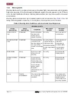
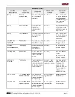
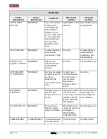
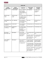
MESSAGES 

VISUAL 

INDICATION 

AURAL 

INDICATION 

CONDITION 

PRE-FLIGHT 

ACTION 

IN-FLIGHT 

ACTION 

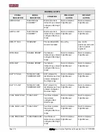
CHECK BARO 
SETTING 

"MESSAGE" 

The current BARO 
setting and the 
nearest METAR-
based altimeter 
setting are more 
than 0.1 INHG apart; 
or, the airplane has 
descended below 
FL180 and the 
BARO should be 
reset. 

Adjust BARO to field 
elevation.  

Adjust BARO setting 
as appropriate.  

CPU TEMP HIGH 

"MESSAGE" 

An SkyView display 
unit

’s internal 

temperature is high. 

Do not fly. 

Increase airflow or 
reduce ambient 
temperature near 
affected display. 

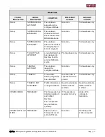
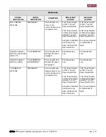
Minimums bug 
appears on Altimeter 

"MINIMUMS" 

Airplane has 
descended below 
set MINIMUM 
altitude. 

No action. 

Pilot awarness only. 

SYSTEM EVENT 
"X": SEE SETUP 

"MESSAGE" 

SkyView has logged 
a system event for 
the Dynon 
Diagnostic file.  

The airplane can be 
flown. 

Contact Dynon 
Technical Support 
for instructions on 
how to provide 
Dynon with a 
Diagnostic File for 
review. 

No action.  

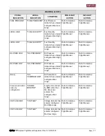
SOFTWARE 
MISMATCH 

"MESSAGE" 

Software versions in 
SkyView HDX 
display units do not 
match. 

Before flight, update 
software to most 
current version in all 
displays in SETUP 
MENU > SYSTEM 
SOFTWARE. 

Do not use SkyView 
HDX display unit 
presenting Red Xs 
over indicators. 

TAIL # MISMATCH 

"MESSAGE" 

Tail numbers in 
SkyView display 
units do not match. 

Before flight, enter 
correct tail number in 
all displays in 
SETUP MENU > 
SYSTEM SETUP. 

Pilot awarness only. 

TIMER EXPIRED 

"TIMER EXPIRED" 

A User-Determined 
timer has expired. 

Pilot determined. 

Pilot determined. 

Summary of Contents for SkyView HDX

Page 1: ...SkyView Airplane Flight Manual Supplement Rev N 10 23 2020 Page i SkyView Airplane Flight Manual Supplement or Supplemental Airplane Flight Manual 103272 000...

Page 2: ...eby grants permission to download a single copy of this manual and of any revision to this manual onto a hard drive or other electronic storage medium to be viewed for personal use provided that such...

Page 3: ...Manual AFM or when no AFM exists used as a supplemental aircraft operating manual when the Dynon Avionics SkyView HDX System is installed in accordance with STC SA02594SE The information contained he...

Page 4: ...improved clarity Added autopilot servo jam emergency procedure Clarified language on FAA approval signature page Formatted section 5 5 Autopilot Operation for improved clarity F 4 29 2019 ECO 327677 C...

Page 5: ...lot Controls o 6 6 Vertical Guidance Source Loss o 6 9 Yaw Damper Updated the following sections of Section 7 Normal Operations for technical accuracy o 7 10 Course OBS Setting o 7 11 HDX Backup Power...

Page 6: ...0 Reorganized document according to GAMA 1 guidelines Aircraft specific information moved to separate Appendices to aid technical reviews of document as more Autopilots are added to airplanes on the A...

Page 7: ...ed old Section 3 1 2 Autopilot Yaw Damper Override to new Section 9 1 1 Subsequent Section 6 headings renumbered Updated language in new Section 3 1 3 Autopilot Yaw Damper Servo Jam Updated language i...

Page 8: ...3 3 4 Normal Operations 4 1 4 1 General 4 1 4 2 SkyView HDX Backup Power Check 4 8 4 3 EFIS D10A Standby Display Backup Battery Condition Check 4 8 4 4 Autopilot Controls 4 8 4 5 Autopilot Operation C...

Page 9: ...utopilot Limitations 10 1 10 2 Autopilot Servo Frangible Link Break Away Forces 10 1 11 Appendix 2 Beechcraft Bonanza P35 through V35B 11 1 11 1 Autopilot Limitations 11 1 11 2 Autopilot Servo Frangib...

Page 10: ...Page x SkyView Airplane Flight Manual Supplement Rev N 10 23 2020 This page intentionally left blank...

Page 11: ...desired altitudes or exceeding engine parameter limits Airspeed altitude and attitude data is collected by the Air Data Attitude Heading Reference System ADAHRS Engine fuel and electrical system data...

Page 12: ...Page 1 2 SkyView Airplane Flight Manual Supplement Rev N 10 23 2020 This page intentionally left blank...

Page 13: ...isibility For all airplanes equipped with EMS Configuring the screen layout of a SkyView HDX display unit so the primary engine instruments are not visible to the pilot is prohibited For twin engine a...

Page 14: ...planes SkyView HDX Synthetic Vision is advisory in nature and must not be used as the sole means of terrain and obstacle avoidance 2 5 Map For all airplanes The SkyView HDX Map and Flight Planning fun...

Page 15: ..._______________________________________ PRESS 2 Pitot Heat Switch _____________________________________________________ ON 3 Maneuver away from icing conditions 4 Choose one Airspeed reads 0 on all in...

Page 16: ..._____________________________ PRESS 2 Flight Controls _________________________________ APPLY BREAK AWAY FORCE 3 Flight Controls _________________________________________________ OPERATE 4 AP Power Sw...

Page 17: ...in Menu indicates STAY ON and POWER OFF 1 STAY ON Button ___________________________________________________ PRESS 2 Plan to land at nearest suitable airport The system is operating on the Backup Batt...

Page 18: ...connect Autopilot 1 Disconnect Autopilot Press and release red AP Disconnect Button either yoke or panel mounted OR Press the AP Button on the Autopilot Control Panel OR Press the AP Button on the Aut...

Page 19: ...and Buttons Knobs are located on the left and right sides of the display They can be rotated both directions and pushed The current knob function is indicated by the soft label above the knob Knob fun...

Page 20: ...s allows the pilot to choose whether a display should show PFD Map or Engine information or some combination thereof See Figure 2 for details for the touchable screen areas of main flight functions Ad...

Page 21: ...the Knob Function Menu then it does not have a touchable screen area and cannot be assigned to the left knob To add or remove bugs to from the Knob Function Menu go to MENU PFD TOOLS BUGS BARO Setting...

Page 22: ...itude After the BARO is synchronized a GPSALT message will appear in the altimeter box on the PFD In the Air Adjusts the altimeter based on the METAR of the flight plan s destination airport if within...

Page 23: ...IN 3 Push knob to close menu menu will also close automatically after 5 seconds This assigns MIN to knob and MIN is shown above knob The Minimum Altimeter area on the PFD is also outlined to show that...

Page 24: ...rce is re selected Knob Control Panel The Knob Control Panel see Figure 3 is an optional panel mounted module for SkyView This control panel has three knobs dedicated to the most common SkyView bug fu...

Page 25: ...ess the knob to select an airport 3 TWR ATIS GND and ATC will now select appropriate frequencies for the selected airport 4 Press the knob to toggle the selected active and standby frequencies 5 Press...

Page 26: ...t failed or the battery is not connected IFR flight with a yellow or red back up battery status indicator displayed is prohibited 4 3 EFIS D10A Standby Display Backup Battery Condition Check The batte...

Page 27: ...for low light visibility but do not indicate autopilot operation status Use the autopilot mode display and or the autopilot menu to determine autopilot operation status Figure 5 SV AP PANEL Horizonta...

Page 28: ...ven if Autopilot is disconnected The level function cannot guarantee recovery below VNE in all starting attitudes due to G limiting and servo effort limiting Recoveries have only been demonstrated fro...

Page 29: ...ce and is tracking a vertical deviation i e status bar shows VNAV or GS as the active mode To engage the Go Around function press the NOSE UP button on the AP Control panel Pressing Go Around NOSE UP...

Page 30: ...u to arm the NAV mode b Press the VNAV button in the Pitch Menu to arm VNAV mode NAV and VNAV modes arm and activate independently from each other There is no limitation upon the order the modes can b...

Page 31: ...controls in the centered position when operating the autopilot on the ground to offset this effect 2 Align HDG TRK bug with current heading 3 Select ALT and HDG 4 Engage Autopilot 5 Set Vertical Speed...

Page 32: ...AUTOPILOT DISCONECT aural should be heard Turn the AP Servo Power switch to OFF and ensure the autopilot disconnects AUTOPILOT DISCONECT aural should be heard Press the AP button on the Autopilot Con...

Page 33: ...rplane Flight Manual Supplement Rev N 10 23 2020 Page 5 1 5 Performance No change to airplane performance Refer to the airplane s Pilot s Operating Handbook and associated Aircraft Flight Manual and s...

Page 34: ...Page 5 2 SkyView Airplane Flight Manual Supplement Rev N 10 23 2020 This page intentionally left blank...

Page 35: ...Flight Manual and supplements Installation of a SkyView HDX system impacts the airplane s level weight and balance once during initial installation Certified installers must add new empty weight and b...

Page 36: ...Page 6 2 SkyView Airplane Flight Manual Supplement Rev N 10 23 2020 This page intentionally left blank...

Page 37: ...yView HDX equipped airplanes always include a Standby Display that provides a display screen and an ADAHRS in a single component with a back up battery to present attitude altitude and airspeed inform...

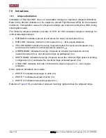
Page 38: ...ents connected to the SkyView HDX Network as appropriate 7 8 Flight Crew Alerting System The Flight Crew Alerting System is a central feature of the SkyView HDX system This system provides the pilot a...

Page 39: ...PILOT DISCONNECT Figure 6 Warning Notification Indication Pressing the WARNING CAUTION or MESSAGE button i e Button 8 opens the Alert Notification Window This window displays text associated with each...

Page 40: ...dio Alert System has failed AoA system will not operate if installed Do not fly Use visual alerts to monitor status BACKUP BATTERY LOW WARNING The Backup Battery connected to the SkyView display unit...

Page 41: ...ystem ADAHRS INTERNAL ERROR WARNING System sensor tests performed on ADAHRS failed Do not fly Monitor Standby Display System ADAHRS FAIL WARNING SkyView HDX has detected a problem with the ADAHRS modu...

Page 42: ...t Manual RPM LOW ENGINE SPEED Tachometer indicator has entered configured Red Low range Refer to Airplane Flight Manual Refer to Airplane Flight Manual EGT X HIGH EXHAUST GAS TEMPERATURE EGT indicator...

Page 43: ...ered configured Red High range Refer to Airplane Flight Manual Refer to Airplane Flight Manual OIL PRES LOW OIL PRESSURE Oil Pressure indicator has entered configured Red Low range Refer to Airplane F...

Page 44: ...lot minimum airspeed Visual annunciation appears immediately Aural warning after 10 seconds No action Take command to manually increase airplane s speed Autopilot Bar changes color and temporarily fla...

Page 45: ...res nose up trim Visual annunciation appears immediately Aural warning after 10 seconds No action Apply Nose Up Trim until the message stops TRIM RUNAWAY shown shown on PFD TRIM RUNAWAY SkyView has de...

Page 46: ...FLIGHT ACTION IN FLIGHT ACTION BACKUP BATTERY IN USE CAUTION The SkyView display unit presenting the alert has switched to Backup Battery power Do not fly Choose one 1 Alert appears on all displays an...

Page 47: ...play unit knob controls Use SkyView display unit knob controls NO HI RES TERRAIN CAUTION No high resolution terrain database is installed for airplane s current position Install high resolution databa...

Page 48: ...rations in Instrument Meteorological Conditions IMC NEED USER AOA CAL CAUTION Angle of Attack AoA calibration for ADAHRS not performed Do not fly if flight requires Instrument Flight Rules IFR Avoid o...

Page 49: ...IFR Use magnetic compass and GPS track for directional reference Avoid operations in Instrument Meteorological Conditions IMC MAG FACT CAL CORRUPT CAUTION The Remote Magnetometer s factory calibration...

Page 50: ...tion XPNDR HEX CODE NOT SET CAUTION Transponder hex code is not entered in SkyView display units If Transponder is required do not fly Enter Transponder hex code in SETUP MENU TRANSPONDER SETUP Advise...

Page 51: ...y and may have specific voice aural annunciations Messages are dependent upon installed systems and components See Table 4 for a full listing of Messages ordered by 1 Core System 2 Component and 3 Fun...

Page 52: ...escended below set MINIMUM altitude No action Pilot awarness only SYSTEM EVENT X SEE SETUP MESSAGE SkyView has logged a system event for the Dynon Diagnostic file The airplane can be flown Contact Dyn...

Page 53: ...w from the external flight plan source Pilot awarness only Pilot awarness only None LEAVING ALTITUDE The airplane is leaving the configured altitude No action Pilot awarness only None TRAFFIC A new tr...

Page 54: ...ilot Bar flashes momentarily AUTOPILOT MODE An Autopilot mode has changed either manually or automaticly since it was engaged Pilot awarness only Pilot awarness only EXT LEVEL BUTTON STUCK MESSAGE The...

Page 55: ...pilot for remainder of flight Slip Skid Indicator Ball turns Green with letters YD YAW DAMPER The Autopilot Yaw Damper has been engaged Pilot awareness only Pilot awareness only Slip Skid Indicator Ba...

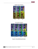
Page 56: ...Indicates minimum control speed VMC twin engine airplanes YELLOW BAND Indicates the range of speeds below the never exceed speed VNE and above the maximum normal operations speed VNO GREEN BAND Indica...

Page 57: ...SkyView Airplane Flight Manual Supplement Rev N 10 23 2020 Page 7 21 Figure 8 Airspeed Marking Examples...

Page 58: ...Operating range For twin engine airplanes SkyView HDX is configured to provide EMS information as follows During takeoffs and landings a secondary non PFD display unit must always present EMS informa...

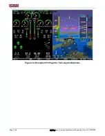
Page 59: ...creen On Single engine airplanes the 100 page see Figure 9 is used only when a display unit has been dedicated to EMS or when operating the engine on the ground for maintenance reasons On Twin engine...

Page 60: ...Page 7 24 SkyView Airplane Flight Manual Supplement Rev N 10 23 2020 Figure 10 Example 100 Display Page for Twin engine Airplanes...

Page 61: ...e engine airplanes the 50 page see Figure 11 is used to provide additional information beyond what is needed for engine operations such as timers and counters On Twin engine airplanes the 50 page see...

Page 62: ...Page 7 26 SkyView Airplane Flight Manual Supplement Rev N 10 23 2020 Figure 12 Example 50 Page for Twin engine Airplanes...

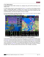
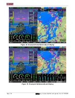
Page 63: ...y On Twin engine airplanes the Bottom Band see Figure 13 can be used to show the required information if the dedicated EMS display unit fails Figure 13 Example Bottom Band for Twin engine Airplanes Th...

Page 64: ...Page 7 28 SkyView Airplane Flight Manual Supplement Rev N 10 23 2020 Figure 14 Example Partial Bottom Band Display Figure 15 Example Full Bottom Band Display...

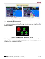
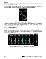
Page 65: ...isual indicators see Figure 17 and aural annunciations CHECK GEAR and GEAR OVERSPEED to alert the pilot to landing gear conditions Figure 17 Example Landing Gear Position Indicator The landing gear s...

Page 66: ...tions are optional and are configured to function during initial system setup Visual indicators and aural annunciations function independently and are configured separately Temperature Indicators Cyli...

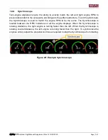
Page 67: ...nchroscope is used to match the engine RPM to be the same The Synchroscope is located between the RPM indicators on all the engine displays When the Synchroscope is rotating clockwise the right engine...

Page 68: ...Page 7 32 SkyView Airplane Flight Manual Supplement Rev N 10 23 2020 This page intentionally left blank...

Page 69: ...airplane Refer to the aircraft s Pilot s Operating Handbook and associated Aircraft Flight Manual and supplements Maintain and service SkyView HDX in accordance with the SkyView HDX General Maintenanc...

Page 70: ...Page 8 2 SkyView Airplane Flight Manual Supplement Rev N 10 23 2020 This page intentionally left blank...

Page 71: ...t modes are annunciated visually on the PFD in a space reserved specifically for this purpose called the Autopilot Information Bar see Figure 22 Visual and voice aural alerts are provided when the Aut...

Page 72: ...al axis modes 4 TAKE OFF PROTECTION Autopilot disengages if engaged when airspeed comes alive 20 kts to prevent the airplane from taking off with the autopilot engaged This allows the autopilot to be...

Page 73: ...the condition of a flight control becoming jammed by an Autopilot servo malfunction The pilot must overcome the servo break away force if a flight control fails to move as expected and is jammed by th...

Page 74: ...n the Autopilot is active and what lateral and or vertical control modes are active and which are armed The AP Info bar resides in the upper left of the PFD see Figure 22 and Figure 23 Touching the AP...

Page 75: ...SkyView Airplane Flight Manual Supplement Rev N 10 23 2020 Page 9 5 Figure 22 Autopilot Information Bar Figure 23 Autopilot Information Bar shown with AP Engaged...

Page 76: ...slip alerts will display in the PFD whenever a servo is unable to move the controls in the direction commanded by the Autopilot See Figure 24 for examples of these alerts and where they are located o...

Page 77: ...rs a Slip Trim Alert for the affected axis When the alert persists the aircraft is likely severely out of trim In this situation disconnect the Autopilot trim the aircraft appropriately and then re en...

Page 78: ...o the selected mode The servos will remain armed in the selected mode until the AP button is pushed Pushing the AP button will engage the servos into the armed mode currently displayed on the Autopilo...

Page 79: ...t to the current indicated altitude VS Maintains the selected vertical speed as airplane performance allows until approaching the altitude bug then transitions to ALT mode NOTE If VS mode is selected...

Page 80: ...e Autopilot Info Bar Go Around The Go Around function is available when the Autopilot is engaged in vertical guidance and is tracking a vertical deviation To engage the Go Around function press the NO...

Page 81: ...uvers The Yaw Damper is engaged independently from the Autopilot and can be engaged when the autopilot is not engaged The Yaw Damper control appears only on the Autopilot Control Menu see Figure 28 To...

Page 82: ...Engaged Indication Table 7 Yaw Damper Disconnect Methods DISCONNECT METHOD AP ENGAGED RESULT Press YD button on AP Control Menu YES or NO Yaw Damper servo disengages autopilot is not affected AP Disco...

Page 83: ...p Setting Use of the Autopilot with flaps extended beyond 10 degrees is prohibited Minimum Altitude Use of the Autopilot below 250 feet AGL is prohibited Servo Frangible Link Use of the Autopilot when...

Page 84: ...Page 10 2 SkyView Airplane Flight Manual Supplement Rev N 10 23 2020 This page intentionally left blank...

Page 85: ...ing Use of the Autopilot with flaps extended beyond 15 degrees is prohibited Minimum Altitude Use of the Autopilot below 425 feet AGL is prohibited Servo Frangible Link Use of the Autopilot when any s...

Page 86: ...Page 11 2 SkyView Airplane Flight Manual Supplement Rev N 10 23 2020 This page intentionally left blank...

Page 87: ...Setting Use of the Autopilot with flaps extended beyond 10 degrees is prohibited Minimum Altitude Use of the Autopilot below 200 feet AGL is prohibited Maximum Climb Descend Rate Use of the Autopilot...

Page 88: ...Page 12 2 SkyView Airplane Flight Manual Supplement Rev N 10 23 2020 This page intentionally left blank...

Reviews: