background image

SV-MAP-270 Navigation Mapping Software 


SkyView Classic Pilot’s User Guide –

 Revision Z 


7-33 


o


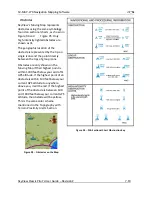
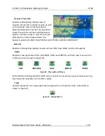
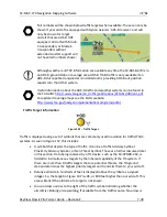
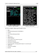
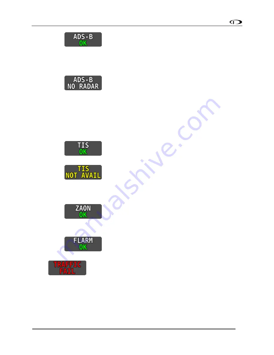
 This signifies that the transponder is communicating with the 

US-based ADS-B ground stations; that those ground stations are replying to the 
ADS-B Receiver; and that your aircraft is in a known radar service volume. This 
allows the ADS-B ground stations to report all ADS-B targets and radar-only 
targets that are not yet ADS-B out equipped, thus providing a full traffic picture. 

o


 The ground-based ADS-B system is reporting that it does not 

have your airplane in radar contact, or that your system is not seeing the ground 
station reporting your airplane is in radar contact. Although you are receiving 
ADS-B traffic from other ADS-B equipped aircraft, you may not be receiving all 
detectable traffic because you may not be currently in a radar service volume 
and ADS-B service volume. Therefore, the traffic portrait may be incomplete. 


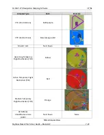
TIS: Traffic provided from an SV-XPNDR-26X, Garmin GTX 330, or any other device that is 
configured to output traffic information in the Garmin TIS format. 

o


 SkyView is receiving traffic data from the device which is 

providing traffic to the best of its ability. 

o


 SkyView is connected to a TIS traffic device, but you are not in 

a TIS service volume (actual TIS devices such as the SV-XPNDR-26X or GTX 330 
only). 


ZAON: A Zaon XRX. 

o


 SkyView is receiving traffic data from the device which is 

providing traffic to the best of its ability. 


FLARM: A device outputting FLARM format data (predominantly in Europe) 

o


 SkyView is receiving traffic data from the device which is 

providing traffic to the best of its ability. 


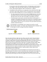
 SkyView is configured for Traffic but there are no devices that are 

currently capable of providing traffic to SkyView. This could be due to failure of traffic 
devices, or an external device that is turned off. 

Summary of Contents for SkyView Classic

Page 1: ...ision Z i SkyView Classic SkyView Touch Pilot s User Guide Document 101321 025 Revision Z For use with software version 15 3 March 2018 Copyright 2009 2018 by Dynon Avionics Inc Permission to print th...

Page 2: ...nd its products register dynonavionics com Register your Dynon Avionics product license dynonavionics com Redeem certificates for Navigation Mapping Software Synthetic Vision and other features for li...

Page 3: ...CH MAY VARY FROM STATE TO STATE AND IN COUNTRIES OTHER THAN THE USA IN NO EVENT SHALL DYNON AVIONICS BE LIABLE FOR ANY INCIDENTAL SPECIAL INDIRECT OR CONSEQUENTIAL DAMAGES WHETHER RESULTING FROM THE U...

Page 4: ...the GPS Source Section Added push to synchronize instructions for applicable bugs Moving Map Operation Chapter updates Added an important note regarding Moving Map requirements Added the GPS Source Se...

Page 5: ...tion about G Meter Added information about new improved Navigation Mapping Software purchase licensing and operation H May 2011 Added description of enabling disabling extreme pitch warning indicators...

Page 6: ...L December 2012 Updated Screen Layout Configuration section to add information about display swap mode and reversion mode Added information about DA calculation Added engine alert inhibit information...

Page 7: ...September 2013 Center click can now be used to pull up set and sync by holding the PFD joystick functions menus bugs baro crs etc Added new Up Down Timers feature Added new Fuel Tank Reminder alert Ad...

Page 8: ...ndly name to aid in identifying sources on the HSI display Moved Synthetic Vision description within the PFD Chapter Added Conventional analog six pack display mode for primary flight instruments Chan...

Page 9: ...ed as a selected airspeed is transitioned through Added Tail numbers for ADS B equipped traffic will be shown below traffic targets when available Only available for aircraft equipped with Dynon Avion...

Page 10: ...rt the pilot when the current BARO setting and the nearest METAR based altimeter setting are significantly different requires SV ADSB 470 472 Added Audible AUTOPILOT callout when the autopilot is enga...

Page 11: ...heating due to failure of SkyView s thermal dissipation features Added New option under MAP MENU MAP ITEMS TFR OPACITY that allows pilots to change the opacity of TFRs This can be used to tune the vis...

Page 12: ...ck Fixed Permanent Disney TFR shown as upcoming instead of active Fixed Filtering for 912iS fuel pressure improved For best results also update to the latest engine sensor definitions Fixed SkyView wo...

Page 13: ...nd balance New Vertical navigation mode New Maintenance Log New Wi Fi streaming data includes weather and traffic data New Highway In The Sky HITS New Airports and flight plan waypoints are shown with...

Page 14: ...ue Changed SV KNOB PANEL synchronization is now a click Changed MDA bug is now labelled MIN Changed Vertical Speed Required VSR index line is now an arrow on the VS tape Changed The north arrow on the...

Page 15: ...AP 270 2 6 SV XPNDR 26X 2 6 SV ADSB 470 472 2 6 SV COM C25 2 7 SV COM X83 2 7 SV INTERCOM 2S 2 7 SV KNOB PANEL 2 7 SV AP PANEL 2 7 Video Input Adapter for SkyView 2 7 Wi Fi Adapter for SkyView 2 8 3 S...

Page 16: ...7 13 MAP Menu 7 34 Navigation and Flight Planning 7 37 Weather and TFR Information 7 79 Glide Ring 7 89 8 Autopilot Operation 8 1 Autopilot Safety Features 8 1 Simplified or Expert Controls 8 2 Top Ba...

Page 17: ...ion 11 11 External Flip Flop 11 13 Dual COM Radios 11 13 12 Messages and Alerts 12 1 Loss of Information 12 1 Message Caution and Warning Alerting System 12 1 Prompts Requiring Interaction 12 5 Audio...

Page 18: ...ng Dynon Avionics products incorporate a variety of precise sensitive electronics SkyView products do not contain any field user serviceable parts Units found to have been taken apart may not be eligi...

Page 19: ...file of this guide to be printed at a large office supply retailer that provides printing services The statement on the cover of this guide Permission to print this manual is granted to third parties...

Page 20: ...elps verify product ownership can expedite warranty claims and allows us to notify you in the event a service bulletin is published for your product You can also optionally sign up to receive other Dy...

Page 21: ...outs Data is sourced from various connected modules and devices Subsequent chapters in this guide address PFD EMS and Moving Map functions in more detail Power SkyView displays require between 10 and...

Page 22: ...n plugged into the unit during use The SkyView Video Input and Wi Fi Adapters also connect via USB These devices must be plugged into the display before power on and remain plugged in for the full fli...

Page 23: ...erview SkyView Classic Pilot s User Guide Revision Z 2 3 configured by the user in the SkyView Setup Menu For more information on configuration retrieval and analysis see the SkyView System Installati...

Page 24: ...all three axes pressure transducers for measuring air data and magnetometers on all three axes for measuring magnetic heading These sensors form the core of Dynon Avionics Air Data Attitude and Headin...

Page 25: ...d well away from any dynamic magnetic interference When installed the SV MAG 236 is the sole source of magnetic heading data to the SkyView System SV EMS 22X The engine gauges on your SkyView Engine P...

Page 26: ...ftware SV MAP 270 SkyView has a robust navigation mapping option that is enabled by a one time licensing of your SkyView system Aviation and Obstacle data is available for free for US based customers...

Page 27: ...with your SkyView System and SkyView COM Radio It has stereo inputs for SkyView stereo music and multiple other mono muting and non muting inputs for all the technology in your cockpit SV KNOB PANEL T...

Page 28: ...additional details The Wi Fi Adapter plugs into a USB port and must be plugged into the display before power on and remain plugged in for the full flight One Wi Fi Adapter is required for each SkyView...

Page 29: ...or acknowledging warnings only need to be performed on one display or control panel to be reflected across the system Some settings such as screen layout and map range level are not synchronized on p...

Page 30: ...guide for details on how to configure the Top Bar The screen shows PFD Engine and Moving Map data configuration information and system alerts Its layout is user configurable See the Screen Layout Con...

Page 31: ...sticks and buttons are used for various functions including powering the unit on and off entering and navigating menus and adjusting values Operation Basics Joysticks can be turned and moved Specific...

Page 32: ...gain At times the next item in the menu path in this guide may be a joystick selection OR a button push the correct choice will be apparent Menu Navigation All menu navigation in this guide starts at...

Page 33: ...e 2 is a summary of menu navigation Desired Menu Action User Action Enter the Setup Menu Simultaneously press and hold buttons 7 and 8 if airspeed is greater than zero you will enter the In Flight Set...

Page 34: ...initely depending on whether or not the aircraft is in flight This feature minimizes backup battery discharge when on the ground and master external power is shut off normally It also reduces pilot wo...

Page 35: ...e brightness of the display to your preference while still allowing SkyView to adjust for changing lighting conditions To decrease or increase the backlight brightness press DEC or INC respectively or...

Page 36: ...em tools which may be useful during flight such as the Flight Angle Pitch Adjust Page and the Angle of Attack Calibration Wizard You may also access the Setup Menu from the In Flight Setup Menu by usi...

Page 37: ...only display data from connected modules For example if an SV EMS 22X module is not present on the network the display will not show any engine data The following table lists the amount of screen spac...

Page 38: ...contents of both displays simultaneously When your screens are in swap mode the PFD PAGE EMS PAGE MAP PAGE and LAYOUT buttons are unavailable Press SWAP again to exit swap mode and revert to normal di...

Page 39: ...ternator or generator is online Specifically If SkyView system voltage is above 12 25V SkyView runs on master power and charges the SV BAT 320 If SkyView system voltage is above 10V but below 12 25V S...

Page 40: ...ctuated Backup Battery Test This can be because o It has been one year since the last full Backup Battery Test See the SkyView System Installation Guide for instructions on how to perform this test o...

Page 41: ...es valid GPS data If installed SkyView s heading will be determined by the SV MAG 236 Remote Magnetometer The heading track altitude vertical speed and indicated airspeed bugs are used to control the...

Page 42: ...s Note that the altitude vertical speed indicated airspeed and heading or track bugs are used for autopilot control if Autopilot servos are installed Instructions for setting bugs are detailed in subs...

Page 43: ...igure 10 Figure 10 All Bugs On For example if the Minimums bug MIN is off it is not an option in the Joystick Menu as illustrated in Figure 11 The same is true for other bugs Figure 11 MDA Bug Off If...

Page 44: ...d down to 15 knots Below 15 knots will again be displayed The indicated airspeed IAS digits scroll up and down simulating an analog Airspeed Indicator The rate of change of the digits provides a sense...

Page 45: ...t left or right to close the menu this is optional IAS will now display just above that joystick The airspeed bug setting on the PFD will be outlined to signal that it is selected Turn the joystick to...

Page 46: ...be degraded and other instruments should be used to maintain safe flight After straight and level flight is restored for a few seconds the ATTITUDE RECOVERING message will disappear Full performance...

Page 47: ...this behavior during slow flight If the aircraft is neither climbing nor descending the flight path marker will align with the zero pitch line Many aircraft do not cruise at an exactly level attitude...

Page 48: ...e change is kept constant the altitude will end up at the number indicated at the end of the trend line after 6 seconds have passed DA will display if an OAT cannot be determined Since relative humidi...

Page 49: ...ug The altitude bug is displayed in cyan on the altitude tape and its associated digital readout is displayed at the top of the altimeter The altitude bug is used as a target for the pitch axis of the...

Page 50: ...idually configurable and the altitude alerter will work even if the autopilot is engaged See the SkyView System Installation Guide for details on how to configure the altitude alerter Minimum Descent...

Page 51: ...d in both analog and digital formats If there is very little or no vertical speed the pointer appears blank When the PFD is configured as a 40 page the digital vertical speed readout appears above or...

Page 52: ...logy and operation information Magnetic Heading Indicator Directional Gyro The Magnetic Heading Indicator Directional Gyro is displayed on the lower center of the PFD and incorporates a magnetic headi...

Page 53: ...wer left of the compass rose To set the heading track bug 1 Enter the Joystick Function Menu 2 Move the joystick up or down to highlight HDG or TRK 3 Click the joystick or move it left or right to clo...

Page 54: ...e sources press HSI SRC in the PFD Menu Back course tracking under AP will only work if the NAV radio has a backcourse mode that reverses sensing E G the SL30 has this in the form of the BC button Cou...

Page 55: ...he CDI make a solid line making it easy to see when there is little error in your aircraft s position Unlike a CDI indicator found in basic aircraft the CDI needle on an HSI rotates with the heading i...

Page 56: ...in available Distance is only shown when only one bearing source is selected Each of the bearing pointers can be cycled between all available bearing sources by pressing BRG 1 or BRG2 in the PFD Menu...

Page 57: ...on and cross wind component are also textually provided If SkyView cannot make an accurate winds aloft calculation the arrow is not displayed and the numbers are replaced by dashes The display of wind...

Page 58: ...ical points When valid GPS data is available the PFD features integrated Synthetic Vision Synthetic Vision displays the terrain directly ahead of the aircraft Terrain is graphically represented in sec...

Page 59: ...nd SV D1000T Operation SkyView Classic Pilot s User Guide Revision Z 4 19 Figure 43 SkyView Synthetic Vision View with Runways Figure 44 SkyView Synthetic Vision Normal View Figure 45 SkyView Syntheti...

Page 60: ...runway in the following manner according to runway width o 0 59 wide no lines o 60 74 wide 4 lines o 75 99 wide 6 lines o 100 149 wide 8 lines o 150 199 10 lines o 200 12 lines Flight Plan Airports a...

Page 61: ...ve situational awareness Figure 46 Traffic Display on Synthetic Vision Traffic information is informational only and does not relieve the pilot in command of his or her responsibility to see and avoid...

Page 62: ...ic Advisories TA all targets or no targets See the SkyView System Installation Guide for information on how to configure how traffic is displayed Note that traffic is not visually scaled for distance...

Page 63: ...other altitude guidance is at the altitude bug even when an external flight plan is being shown HITS is intended to be used for enroute flight and during SkyView generated Vertical Guidance Figure 51...

Page 64: ...n 10 0 or later SkyView includes the traditional six pack analog presentation of flight instruments as well as the EFIS tape based display SkyView s six pack flight instrumentation mode lets you fly t...

Page 65: ...on Z 4 25 Figure 53 Analog PFD with Synthetic Vision Figure 54 Analog PFD without Synthetic Vision To turn on the six pack SynVis or EFIS presentation go to the PFD Menu MODE and select the layers to...

Page 66: ...banners Flight Director and bugs etc appear just like they do for the EFIS tapes However EFIS tapes are required to view the Extreme Pitch Warning Indicators The six pack presentation can be turned of...

Page 67: ...he same on all ADAHRS Parameters that are continuously cross checked include attitude pitch and roll magnetic heading G Meter turn coordinator slip skid ball airspeed and altitude Figure 55 ADAHRS Cro...

Page 68: ...lot s User Guide Revision Z 4 28 Figure 56 ADAHRS Cross Check Comparison Once you have determined which ADAHRS is incorrect press DISABLE to tell SkyView not to use it for the duration of the flight F...

Page 69: ...u do not disable an ADAHRS a red warning and ADAHRS CROSS CHK ERROR alert will persist in the Message Alert Area above button 8 To go back to the ADAHRS comparison screen to disable an ADAHRS see the...

Page 70: ...t normally won t be chosen for display on the PFD unless the primary ADAHRS has failed or has manually been disabled To change which ADAHRS is the PRIMARY ADAHRS highlight an ALTERNATE ADAHRS and pres...

Page 71: ...craft G limits are being approached Instantaneous G information is also shown digitally in the center of the gauge Figure 60 G Meter on PFD The smaller digital numbers above and below the larger insta...

Page 72: ...sourced from SkyView s own Navigation Mapping Software these are all external navigation devices such as other portable GPS units such as the Garmin 496 panel mounted IFR GPS systems such as the Garm...

Page 73: ...or is described here All other Top Bar behavior is covered in the relevant chapter of this guide The clock is part of the Top Bar which is always displayed regardless of the screen layout The clock is...

Page 74: ...cknowledge this alert If a DOWN timer is not reset the timer will continue to count down negatively o When the UP timer is running it will stop at 99 59 minutes RUN Turns the timer on and off RUN is h...

Page 75: ...Z 4 35 Note that your checklist will continue to be displayed until the CHECKLIST button is pressed again or the X in the corner is touched If the menus change return to the main menu push the TOOLS...

Page 76: ...pty weight its arm and moment defined various loading stations specified the aircrafts CG limits and whether they are metric values To access the Weight and Balance Calculator on your SkyView display...

Page 77: ...e Log on your SkyView display from the main menu go to the TOOLS menu and push the MAINTENANCE button The Maintenance Log will display any a list of items tracked for maintenance either in chronologic...

Page 78: ...ck Bug HDG TRK on the primary flight display These knobs behave exactly like the SkyView joystick knobs do when they are set to these functions turn them to adjust the value they control Press and hol...

Page 79: ...ayout The three Engine Pages 100 50 and 20 should have been configured during installation The appearance of the 20 and 50 Engine Pages are not scaled down versions of the 100 Engine Page They are uni...

Page 80: ...Message Window when they enter their red ranges In other words yellow caution ranges for engine parameters do not trigger alerts Yellow caution ranges however are visually annunciated via yellow high...

Page 81: ...oil temperature behave in the following ways Tachometer for Rotax 912 When OIL TEMP 120 F the TACHOMETER displays these ranges 0 1400 and 4000 6000 RPM in RED 1400 1800 and 2500 4000 RPM in YELLOW 18...

Page 82: ...that point The engine monitor also includes a leaning function to automate this process To activate leaning mode press LEAN With this mode activated LEAN highlights and the label LEAN is displayed un...

Page 83: ...ow your engine manufacturer s leaning recommendations for best performance On some engines when given the proper set of inputs the EMS can also calculate lean of peak or rich of peak operation in real...

Page 84: ...imer labeled RUN TIME when displayed on an Engine Page is a Hobbs style timer that records the time your engine has been running during your current flight It resets the first time the engine is start...

Page 85: ...Screen Layout Editor reference the SkyView System Installation Guide The Fuel Remaining info item displayed as FUEL REM displays the current amount of fuel computed on board based on your input of th...

Page 86: ...ent Fuel Computer Quantity is the total amount of fuel on board as far as the fuel computer knows This is the number that ultimately needs to be correct in order for the fuel computer to accurately pe...

Page 87: ...ank fuel quantity sensors does not closely match the fuel computer s fuel remaining value Dual Engine Monitoring For aircraft with two engines SkyView can be configured to monitor both engines when tw...

Page 88: ...lling a VP X license on a SkyView system and configuring SkyView to properly interface with the VP X can be found by referencing BOTH the Dynon SkyView System Installation Guide and the Vertical Power...

Page 89: ...ng displayed when the VP X page is toggled on the Map Page will automatically be removed to accommodate the VP X page When you turn the VP X page off the Map Page will automatically be re opened Figur...

Page 90: ...e enabled in the VP X setup process The center column displays the name of the circuit The column to the left of the circuit name is blank when the circuit is turned off displays a green checkmark whe...

Page 91: ...s described in the VP X documentation Depending on the VP X configuration a single quick press of the UP or DOWN button may move the flaps to a preconfigured angle or notch of flaps Or it may only mov...

Page 92: ...DS B OUT messages via its 1090ES capability The SV XPNDR 26X transponder is controlled using the SkyView s on screen menu system This allows the transponder to be mounted separately from the instrumen...

Page 93: ...ll interrogations f IDT Displayed while the transponder is broadcasting an ident after the IDENT button is pressed at ATC s request g Big red X covering entire transponder status area Indicates an err...

Page 94: ...t the transponder in standby mode ON Press to set the transponder to respond to all interrogations but with altitude reporting suppressed When active the ON button will remain highlighted in this menu...

Page 95: ...Transmissions If SkyView has a valid GPS signal and a SV XPNDR 26X module is installed and working it automatically provides ADS B output at the appropriate integrity level for the GPS signal being us...

Page 96: ...OUT If you do not have a certified GPS navigator on board but do have a Dynon Mode S transponder the appropriate ICAO Surveillance Equipment Code is S FAA Flight Plans If your aircraft is equipped wi...

Page 97: ...p will be available once the message clears Beginning with SkyView software version 3 0 the SV MAP 270 Navigation Mapping Software is available for purchase The Navigation Mapping Software replaces th...

Page 98: ...stores the license is not returned to the system when this countdown expires the display will revert to an unlicensed state This feature is intended to allow the map to continue to function in the ev...

Page 99: ...ETUP LICENSE LICENSE CODE If you have more than one display in the aircraft choose one to install it onto and provide information for only that display Once any display is licensed all connected displ...

Page 100: ...ers downloadable high resolution terrain data files for other regions of the world on its website at www dynonavionics com docs terrain html To update the terrain data in a SkyView display download th...

Page 101: ...nd download PocketFMS AeroData visit their website at www pocketfms com dynon Worldwide Customers Jeppesen NavData and Obstacle Data Services Aviation and Obstacle for customers outside the US is avai...

Page 102: ...you have the Map Page up on other displays you may see a SYNCHRONIZING DATABASES message appear as this process occurs If you do not have your displays connected via Ethernet simply load the database...

Page 103: ...visual approach landing and area charts critical to flight in Europe are available for many countries We encourage you to contact PocketFMS directly to best understand what exact charts are offered in...

Page 104: ...re all available for an unprecedented price This includes all available VFR and IFR data in one flat rate Only one subscription is needed per airplane Preparing USB Memory Sticks for Use Seattle Avion...

Page 105: ...l Seattle Avionics ChartData on your USB memory stick s that have been prepared per the above procedure After you have installed ChartData to your USB memory sticks simply connect them to your SkyView...

Page 106: ...e that neither German DFS charts nor Swiss SkyGuide VFR Plates are included in this price but they are available at additional cost Once you have registered and paid for your Frequent Flyer membership...

Page 107: ...ructions for physically installing electrically connecting and configuring a GPS device to work in a SkyView system This guide assumes these steps have been properly executed You should be familiar wi...

Page 108: ...items are displayed on the Moving Map Page shown in Figure 80 Topography terrain and bodies of water with Terrain Proximity Alerting Default Aircraft Icon with Ground Track Line Distance Circle and R...

Page 109: ...justed to suit your preference See the SkyView System Installation Guide for details The Yellow red terrain alert coloration does not appear on the map until the aircraft is in flight Aircraft Icon wi...

Page 110: ...ion over the ground the aircraft will be when it intercepts the altitude bug It will not show if the vertical speed is not in agreement with the altitude bug for example if the aircraft is descending...

Page 111: ...he SkyView System Installation Guide instructions on how to change the displayed Aircraft Icon Symbol Distance Circle The distance shown on the map between the aircraft icon and the inner circular rin...

Page 112: ...k Figure 88 Ground Track Arc The current ground track as shown in Figure 89 is displayed in two ways the digital readout and the white ground track line The border around the digital readout is normal...

Page 113: ...on Mapping Software is navigating to an active waypoint It is the shortest path between the two points that it connects on the map Figure 92 Course Line Flight Plan Legs Flight plan legs appear in the...

Page 114: ...SV MAP 270 Navigation Mapping Software SkyView Classic Pilot s User Guide Revision Z 7 18 Figure 93 Flight Plan Legs...

Page 115: ...rectly between the tips of group icons Obstacles are only shown on the Moving Map if their highest point is within 1000 feet below your aircraft s GPS altitude If the highest point of an obstacle is w...

Page 116: ...in Table 6 The floors and ceilings of airspaces are shown within each airspace segment in the familiar sectional style notation Airspace Type Color Example Class A Solid orange with interior shading...

Page 117: ...areas that extend to the surface in US depictions Solid green with interior shading Restricted and Prohibited Solid orange with ticks marks Warning Caution Training and Alert Areas Yellow tick marks n...

Page 118: ...mple CTA Control Area Solid purple CTR Control Zone Blue orange solid Mode C Veil Not shown None Upcoming Temporary Flight Restriction TFR Yellow Active Temporary Flight Restriction TFR Red Stadium Te...

Page 119: ...s selected in MAP MAP MENU MAP ITEMS AIRSPACE PROXIMITY Navaids SkyView s Moving Map displays navaids such as VORs fixes NDBs and User Waypoints VORs SkyView s moving displays VORs VOR DMEs DMEs and V...

Page 120: ...nd a text name If more information is provided in the database a modifier may be added to the icon A line in the circle represents the direction of the primary runway Other symbology may be used in th...

Page 121: ...igure 102 Places on Moving Map Motorways Primary Roads Railroads and Rivers SkyView displays motorways as thick solid black lines primary roads as thinner solid black lines railroads as thin dark line...

Page 122: ...a Once you enter the MAP menu this message can be cleared until the next power up Map Items on Charts To reduce visual clutter on charts map items from SkyView s databases will only appear on top of a...

Page 123: ...o more filters First SkyView will not display airspace sectors above the altitude chosen in feet in the HIDE AIRSPACES ABOVE option Second SkyView will only show airspace sectors within the chosen ran...

Page 124: ...ed by the SV XPNDR 26X or Garmin GTX 330 330ES Transponders passive traffic from the Zaon XRX FLARM predominantly in Europe and the NavWorx ADS B receivers Traffic is displayed on the Map Page in the...

Page 125: ...Additionally the FAA s ADS B TIS B service seeing your transponder s 1090ES ADS B out transmission but knowing that your aircraft only has 978 MHz input capability via the SV ADSB 470 assembles a traf...

Page 126: ...ttp www faa gov nextgen implementation programs adsb Traffic Target Information Figure 107 Traffic Target Traffic is displayed using a set of symbols that are commonly used in aviation for traffic TCA...

Page 127: ...or no targets See the SkyView System Installation Guide for information on how to configure how traffic is displayed Traffic Advisory TA Targets Figure 108 Traffic Advisory TA Symbol Figure 109 TA Sym...

Page 128: ...Traffic Advisory Targets nor Proximity Advisory Targets Traffic Coasting Traffic directly received from ADS B equipped aircraft is normally updated once per second TIS B traffic derived from radar co...

Page 129: ...rently in a radar service volume and ADS B service volume Therefore the traffic portrait may be incomplete TIS Traffic provided from an SV XPNDR 26X Garmin GTX 330 or any other device that is configur...

Page 130: ...DR 26X Garmin GTX 330 when in an active TIS coverage area 3 Flarm device 4 Zaon device Traffic Alert Figure 113 Traffic Alert The above alert is shown on both the PFD Page near the top of the IAS tape...

Page 131: ...e CURSR joystick down to find the desired item by identifier facility or city Or move the CURSR joystick left to the RECENT tab to choose from the most recently used and viewed airports and navaids FP...

Page 132: ...sectionals world area terminal area charts in the US IFR LOW Pressing the IFR LOW button displays Geo referenced IFR low altitude enroute charts IFR HIGH Pressing the IFR HIGH button displays Geo refe...

Page 133: ...course information can be displayed on the SkyView PFD s HSI display when it is selected and navigating to an active waypoint It is always labeled SKYVIEW in the HSI and in the Flight Planning window...

Page 134: ...o select the next character and continue until the desired facility is shown Alternatively if you move the CURSR joystick left after the first press of the INFO button you can choose from the most rec...

Page 135: ...dow Filtered Each tab in the bar of tabs at the top of the Nearest window contains a list of aviation features they include APT Airport WX Weather when a weather device is connected VOR NDB FIX Fixes...

Page 136: ...is active o RUNWAY SURFACE The pilot can choose to display Any Surface Water only Hard and Soft or Hard only when FILTER is engaged o PRIVATE AIRPORTS The pilot can choose to Show or Not Show private...

Page 137: ...o return to the full list press You may press ADD FPL from the info window to add the displayed facility as a waypoint to the Flight Plan You may also press the TUNE COM button to send the selected fr...

Page 138: ...nt types of facilities includes Name Type public military private VOR NDB etc Identifier Current distance bearing to facility Region Field elevation Parking availability Communications and Localizer f...

Page 139: ...for a waypoint by identifier name or city If navigation is already active the current waypoint will be shown You may also select the RECENT tab of the Info window to find waypoints that have been nav...

Page 140: ...press FPL FPL MENU select CLEAR FLIGHT PLAN and then move the joystick right twice once to select twice to confirm to clear all waypoints from the flight plan and cancel navigation simultaneously Thi...

Page 141: ...on to the Map Pointer a Map Pointer Information Bar displays the following information about the Map Pointer Latitude Longitude Distance between the Map Pointer and the aircraft Magnetic bearing from...

Page 142: ...cludes items such as airports airspaces navaids waypoints obstacles and cities To select an item simply use the Map Pointer to point directly at the item After a couple of seconds the item is highligh...

Page 143: ...etween each waypoint defines the individual legs of the Flight Plan When a Flight Plan is active and shown on the Map the current leg is magenta in color Future legs are white Extended Runways When th...

Page 144: ...ath is indicated in the VSI In a series of figures on the next page the blue tick mark shown on the VSI represents the vertical speed necessary to descend along a path calculated at the defined angle...

Page 145: ...SV MAP 270 Navigation Mapping Software SkyView Classic Pilot s User Guide Revision Z 7 49 Figure 129 Figure 130 Figure 131...

Page 146: ...DD POINT TO FPL or by importing a Flight Plan file from a USB memory stick in GPX format Operations are performed on the flight plan via the FPL MENU Flight Plans from external ARINC and Aviation seri...

Page 147: ...o a USB Memory Stick See http wiki dynonavionics com Importing_Flight_Plans for information about specific aviation software products that are known to output compatible GPX files Additionally a techn...

Page 148: ...lected destination waypoint OF overfly Icon This indicates the transition type of the leg When OF is present the leg ending at this waypoint has an overfly transition otherwise it has a flyby transiti...

Page 149: ...is active FPL MENU Press to bring up the FPL MENU The FPL MENU provides access to various operations that can be performed on the Flight Plan and its waypoints Reference the FPL MENU section below for...

Page 150: ...SkyView and ForeFlight customers US and Canada only can send and receive flight plans between SkyView and their ForeFlight Mobile app on Apple iPad iPhone and iPod Touch devices running the iOS opera...

Page 151: ...Settings Icon or in the Devices list Figure 135 Map Settings Menu Figure 136 Devices Menu Lastly to allow SkyView to receive flight plans from a connected ForeFlight app confirm that Allow Incoming F...

Page 152: ...SV MAP 270 Navigation Mapping Software SkyView Classic Pilot s User Guide Revision Z 7 56 Figure 137 ForeFlight Flight Plan...

Page 153: ...eives the flight plan a confirmation message will appear on the map and the Flight Plan will be in SkyView s Flight Plan window The flight plan can then be used and edited on SkyView Figure 139 ForeFl...

Page 154: ...nformation is GPS based See the ForeFlight documentation for a full description of how flight instrumentation is displayed within the app You can confirm that SkyView is ForeFlight s source of attitud...

Page 155: ...l appear under the FP tab This indicates that EasyVFR is now constantly monitoring your Wi Fi network to see if a SkyView unit is announcing its presence As soon as EASYVFR finds your SkyView the wait...

Page 156: ...plans are only updated when you explicitly send or receive them from the EasyVFR app This ensures that no flight plan changes are made to either EasyVFR or SkyView s flight plan without explicit actio...

Page 157: ...ight plan SET OBS MODE Select to turn on OBS mode using the selected waypoint When OBS Mode is active you can then adjust the inbound course to the waypoint using the CRS function of the PFD joystick...

Page 158: ...the FPL MENU Note that this is different from receiving a flight plan from ForeFlight over Wi Fi That action is solely done in the ForeFlight app SHOW SKYVIEW FPL ON MAP or SHOW _EXTERNAL NAVIGATOR_...

Page 159: ...n passed SkyView automatically extends the active leg indefinitely TRN TOO STEEP Displayed when the required bank to complete the upcoming turn as depicted on the map is excessive Figure 145 Flight Pl...

Page 160: ...e selected leg The following figure shows an active Flight Plan where the first leg is active and the aircraft is partway between the first two waypoints of the Flight Plan and is on course The route...

Page 161: ...T OBS MODE The flight plan display will surround the waypoint that OBS Mode is set on with OBS MODE and FPL SUSPENDED messages When OBS Mode is active normal flight plan leg sequencing is suspended an...

Page 162: ...FPL MENU CANCEL OBS MODE Alternatively you can perform any action that would cause SkyView to navigate somewhere else Examples of this include Activate a different leg on the flight plan by using the...

Page 163: ...ort Diagrams Turn the CURSR joystick knob to select from a list of the available charts diagrams A preview of the chart is shown below the list To view a chart on the map page press VIEW Zooming Panni...

Page 164: ...t Viewed Chart To quickly return to the last chart that was viewed With the normal map page displayed press click and hold the joystick knob for 1 2 second o When you are within 300 feet AGL of at an...

Page 165: ...rts Tab with Preview Figure 153 Full View Figure 154 Full Width View Figure 155 Following Enabled SkyView User Waypoints SkyView supports the ability to create manipulate and import export User Waypoi...

Page 166: ...6 Waypoint Tools in the Map Menu Move the CURSR joystick up and down to move the cursor between the various fields Turn it to select characters The editable fields include Identifier Like other airpor...

Page 167: ...y from a properly formatted CSV comma separated values file on a USB memory stick A USB memory stick must be connected to the display that you perform this operation from Imported waypoints are added...

Page 168: ...remarks tab on the Info Page Upper and lower case characters can be used If your narrative text contains any commas and you are editing in plaintext enclose the entire narrative text section in quote...

Page 169: ...g User Waypoints User Waypoints are searchable via the USER tab on the Nearest window The USER tab only appears if there are User Waypoints stored in SkyView User Waypoints can also be found like any...

Page 170: ...ther the left or right joystick knob to the MAP when the Map Page is full screen NEAREST LIST OPTIONS Use these settings to choose whether or not the NRST list shows full airport names or not and to a...

Page 171: ...t o ETA Final The estimated time of arrival at the final waypoint in the flight plan This time does not account for time zone changes If GPS ground speed is 25 knots the Plan Ground Speed setting MAP...

Page 172: ...nificantly from your barometric indicated altimeter due to variations in the GPS data model GPS accuracy and nonstandard variations in outside pressure o Ground Speed o Next Course The direction from...

Page 173: ...or other waypoint selected in the Info Nearest Flight Plan or Map Pointer pages If there is an active flight plan touching and the current waypoint will appear on the resulting info page FPL Page Tap...

Page 174: ...Mapping Software SkyView Classic Pilot s User Guide Revision Z 7 78 NRST Page_ Tap NRST Nearest to bring up the window that displays the nearest airports navaids and user waypoints Figure 159 Touch Sh...

Page 175: ...B weather reception may not be continuous Due to latencies that accumulate while NEXRAD weather images are created and the way that the FIS B NEXRAD services timestamp weather data NEXRAD images are a...

Page 176: ...ecasts wind direction relative to true north wind speed knots and temperature Celsius for specific altitudes in feet above mean sea level NEXRAD Radar Imagery NEXRAD radar transmits short high frequen...

Page 177: ...472 is connected and configured MAIN MENU MAP LAYERS opens the layers menu that allows you to depict weather on top of any of the other layers Pushing the WEATHER button will toggle the NEXRAD overla...

Page 178: ...SV MAP 270 Navigation Mapping Software SkyView Classic Pilot s User Guide Revision Z 7 82 Figure 161 Map Page Weather Only View Figure 162 Map Page Terrain and WX View...

Page 179: ...have NEXRAD imagery available This may be the case if Data is not available for the area because there is no NEXRAD coverage in the locale This can be observed in the areas surrounding the US in Figu...

Page 180: ...eceiver This block only appears on the Moving Map when the WEATHER Layer is currently displayed Figure 166 Data Current Figure 167 Data Stale Figure 168 Data Expired Figure 169 ADS B Receiver Not Foun...

Page 181: ...reports for airports that report METAR information can be found in the NRST list Nearest Weather The MAIN MENU MAP NRST window will contain a WX weather tab whenever weather information is available t...

Page 182: ...weather reports are available for an airport they are accessed by selecting the WX tab the INFO window for that airport Those reports can also be displayed as colored icons for the airport icons on t...

Page 183: ...SV MAP 270 Navigation Mapping Software SkyView Classic Pilot s User Guide Revision Z 7 87 Figure 171 METAR Decoded Figure 172 TAF Decoded Figure 173 METAR TAF RAW Figure 174 Winds Aloft Forecast Text...

Page 184: ...able o Expired red Data is older than the end of the TAF forecast period TFR Depiction Known published TFRs both upcoming and active TFRs are depicted on the map page as shown below After the TFR expi...

Page 185: ...der MAP MENU MAP ITEMS TFR OPACITY Figure 177 Upcoming TFR Figure 178 Active TFR Figure 179 Stadium TFR Glide Ring When the Sink Rate During Glide and the Best Glide parameters are set properly in SET...

Page 186: ...r Guide Revision Z 7 90 Figure 180 Example Glide Ring In this figure note how the ring is offset behind the aircraft due to a strong headwind Also note that attempting to reach KVCV is a better choice...

Page 187: ...e Autopilot circuit breaker or fuse on in the aircraft will completely inhibit the Autopilot servos from controlling the airplane However SkyView does continuously look for the presence of powered up...

Page 188: ...ilots need to complete their mission including VNAV IAS Hold mode sequencing fully coupled approaches a Flight Director with single cue v bars or dual cue crosshairs presentation and more Each of thes...

Page 189: ...e autopilot is disengaged To eliminate the excessive trim forces that the autopilot is trying to overcome trim the nose of the aircraft in the direction indicated up or down Adjust the trim in small i...

Page 190: ...dicated left or right Adjust the trim in small increments and wait a few seconds between adjustments to see whether the adjustment is sufficient to remove the out of trim indication This alert may not...

Page 191: ...ed and Expert Control sections below for additional Control Wheel Steering behavior information Figure 188 Control Wheel Steering Mode Indicator The Control Wheel Steering feature can be enabled and d...

Page 192: ...nt Therefore when GPS ASSIST is active SkyView cannot limit operations to the maximum and minimum airspeeds as described in this section Use extreme caution when using the autopilot under this circums...

Page 193: ...slip annunciation is being shown If persistent servo slip alerts are accompanied by trim up down left right alerts the Auto Trim feature many not be able to achieve its goals This could be due to an...

Page 194: ...ton to return to the Main Menu OFF Press the OFF button to disengage both servos from any mode YD Engages and disengages the yaw damper separately from roll and pitch servos Button is not shown if the...

Page 195: ...is available to SkyView VOR and LOC sources can still be flown by the autopilot but the autopilot s ability to perfectly track the course guidance may be reduced LEVEL Press the LEVEL button to engage...

Page 196: ...the aircraft was flying in the moment before the autopilot was engaged After the autopilot is engaged change the track you want the autopilot to fly by adjusting the TRK bug HSI GPS GPS In HSI mode t...

Page 197: ...controlled changes in altitude is governed by the VS vertical speed bug When the autopilot is engaged and a new altitude is selected the Autopilot will automatically choose one of two preset default...

Page 198: ...ilot s altitude target is synchronized to the aircraft s current altitude o Roll axis No change The roll axis resumes tracking its HSI source The Control Wheel Steering feature can be enabled and disa...

Page 199: ...dual axis installation described earlier except that only ALT mode functionality is provided Yaw Axis only Single servo control of only the yaw axis is supported Expert Autopilot Operation and Control...

Page 200: ...topilot See the Roll Menu section below for details YD Engages and disengages the yaw damper separately from the pitch and roll servos LEVEL Press the LEVEL button to engage the autopilot in Level mod...

Page 201: ...s ROLL HOLD Activates Deactivates roll hold mode ROLL HOLD will be unavailable and grayed out if the autopilot is outside of its allowable engagement speed ranges Pitch Menu The Expert Autopilot Pitch...

Page 202: ...the VS target thereby causing the autopilot to pitch the nose of the aircraft down IAS mode Raises the IAS target thereby causing the autopilot to pitch the nose of the aircraft down ALT HOLD mode Imm...

Page 203: ...ray background indicates that a mode is armed and will become active when the autopilot detects the capture criteria for the armed mode have been met A black background indicates that the mode or func...

Page 204: ...rn the flight director off regardless whether the autopilot was engaged Press the AP button to disengage the servos while leaving the flight director active with all active and armed modes unchanged F...

Page 205: ...the selected navigation source Automatically sequenced from the NAV armed mode NAV GPSS Active GPSS NAV VOR Active VOR NAV LOC Active LOC Level Mode STRAIGHT Holds the aircraft in a wings level attit...

Page 206: ...the top bar will blink for 10 seconds When your HSI source is a radio based VOR or LOC SkyView uses GPS position information to help the autopilot correct for wind effects If no GPS is available to Sk...

Page 207: ...e aircraft s current VS is used as the target VS and the VS bug is synchronized accordingly The vertical speed target can be adjusted with the VS bug the NOSE UP DN menu buttons or utilizing Control W...

Page 208: ...he NOSE UP DN menu buttons for small adjustments or utilizing Control Wheel Steering Note that changing the altitude bug does not affect alt hold mode when it is active This allows you to use the alti...

Page 209: ...VNAV always causes ALT HOLD to engage with the VNAV mode armed Only when the glideslope or VNAV Indicator next to the HSI can be captured as the GS VNAV indicator comes alive will the Autopilot sequen...

Page 210: ...uctions on how to change the type of flight director used Control Wheel Steering When the autopilot is engaged press and hold the Autopilot disconnect switch to put the autopilot into Control Wheel St...

Page 211: ...utilize the Expert Autopilot controls the autopilot will function with a single axis turned off or one or both servos failed With the autopilot on a single axis can be turned off by pressing the butt...

Page 212: ...weren t already climbing or descending initiate a climb or descent with the NOSE UP DN buttons either in the PITCH menu or on the Autopilot Control Panel to adjust the autopilot s target airspeed Or...

Page 213: ...send a signal to the SkyView to automatically change the HSI source at the appropriate time If your external GPS NAV device is configured with this behavior enabled one important detail is that such...

Page 214: ...topilot Control Panel provides dedicated controls for all Autopilot modes This allows the pilot to navigate other menus on the SkyView display while retaining direct access to the autopilot Autopilot...

Page 215: ...ng installation Trim Controller Safety Features Controlling aircraft trim in your aircraft is serious The SV AP PANEL s integrated trim controller features the following safety features When the trim...

Page 216: ...The touch interface philosophy is derived from SkyView s complete set of buttons and joystick knobs so you don t have to learn any different processes for turbulence when you can rely on the buttons a...

Page 217: ...will shortcut to AUTOPILOT PITCH 2 MAIN MENU XPNDR 3 MAIN MENU TOOLS TIMER PFD Operations Touching a PFD item that has an adjustable bug instantly re assigns a SkyView PFD joystick knob to that touche...

Page 218: ...nt navigation data sources that are connected to the SkyView system 8 Assigns knob to MDA bug if MDA bug is turned ON in the PFD menu 9 Equivalent to pressing MAIN MENU PFD so that the pilot can adjus...

Page 219: ...raft 3 The and will zoom the map in or out In addition you can use two fingers anywhere on the map to pinch to zoom in or out of any point or area of interest 4 Touching any of the shortcut info item...

Page 220: ...en multiple possible items can be selected on the map 6 Touch the North arrow to toggle the map display between track up and north up mode Unlike the preference setting in MAP MENU MAP MODE this is no...

Page 221: ...change the menu and any open windows will close just as if CANCEL BACK had been pressed For example if you are adding a waypoint to the SkyView flight plan and touch the top bar for the TIMER before...

Page 222: ...SkyView Touch SV D1000T Operation SkyView Classic Pilot s User Guide Revision Z 9 7 Figure 222 Touch QWERTY Keyboard Entry...

Page 223: ...hat are used for loading software loading databases and storing charts SkyView s video input capability is only available when SkyView recognizes a connected Video Input Adapter when it is powered on...

Page 224: ...T Operation SkyView Classic Pilot s User Guide Revision Z 10 2 Figure 223 Full Screen Video Display Figure 224 Half Screen PFD Video Display Figure 225 Half Screen EMS Video Display Figure 226 Half Sc...

Page 225: ...SkyView COM radio from SkyView s airport info pages And of course you can also spin frequencies in the old fashioned way when you re feeling nostalgic or are following ATC instructions The airport loo...

Page 226: ...COM Radio normally powers on and off with your SkyView system Press and hold the Volume Knob Power Button to manually turn the SkyView COM Radio off and on Volume Use the volume knob to adjust the rad...

Page 227: ...e active transmissions on them However you may wish to override this feature to hear a distant radio station or to help set the radio volume To listen to the active frequency press the volume knob mom...

Page 228: ...andby frequency For example if ATIS is on standby and tower is on active and dual watch is enabled the COM will receive ATIS continuously on standby when there is no tower activity But when a tower tr...

Page 229: ...op the chosen frequency from the standby frequency to the active frequency Airport Station Type Reverse Lookup When a frequency is manually tuned SkyView will search for the closest known airport with...

Page 230: ...quency Press the dual concentric knob on the control panel to flip flop the chosen frequency from the standby frequency to the active frequency This feature also works when a Garmin SL30 SL40 GTR 225...

Page 231: ...ive feature is its ability to load airports onto the control panel Once an airport is loaded single presses of the TWR ATIS GND and ATC buttons automatically tune those frequencies to the standby loca...

Page 232: ...O page Press the APT COM button to load the airport to the control panel o Note this button is only available if SkyView has frequencies for the selected airport Use the TWR ATIS GND and ATC buttons t...

Page 233: ...al concentric knob to the airport you wish to load Press the dual concentric knob on the control panel to load the airport to the control panel or press APT to cancel your selection Use the TWR ATIS G...

Page 234: ...ayed press the dual concentric knob on the control panel to load the airport to the control panel or press APT to cancel your selection Use the TWR ATIS GND and ATC buttons to send the associated airp...

Page 235: ...encies can be tuned at any time Other Status Information Operating Without SkyView The SV COM C25 can be used when SkyView is powered off or has failed However only manual tuning will be available and...

Page 236: ...top bar annunciate that SkyView does not have GPS position information in the following way Without GPS position airport loading and TWR ATIS GND ATC will not be available You may see this annunciatio...

Page 237: ...ore than one COM radio that is capable of communicating with SkyView only the primary COM radio s status information will be displayed in the Top Bar Additionally only the primary radio will receive a...

Page 238: ...that prevents the display of information A red X may overlay an entire page if a data source such as an EMS module fails or a red X may overlay a single widget if a single engine sensor fails or is n...

Page 239: ...ication Style Alert Type Flashing Unacknowledged Advisory Message Flashing Unacknowledged Caution Alert Flashing Unacknowledged Warning Alert Solid Persistent but acknowledged Advisory Message conditi...

Page 240: ...s configured as off no alert will trigger even if that sensor s measurement enters a range defined as red Reference the SkyView System Installation Guide for more information regarding alarm configura...

Page 241: ...dged left and Acknowledged right Alarms Note that even when all alerts are acknowledged the Message Notification Area will remain solidly red yellow or white as long as an alert condition or message p...

Page 242: ...Audio alerts that occur within 5 seconds of SkyView initially powering on are inhibited to reduce transient nuisance alerts that may occur as SkyView comes online Engine Alerts can be optionally confi...

Page 243: ...on demo mode and is not airworthy Warning ARINC 429 OFFLINE The SV ARINC 429 module is not communicating with SkyView Warning BACKUP BATTERY LOW The backup battery connected to this display is low War...

Page 244: ...netometer has failed or is no longer communicating via SkyView Network Caution NEED USER AOA CAL AOA is not properly calibrated Caution CHECK PITOT HEAT Airspeed information is not available GPS is be...

Page 245: ...is no longer communicating with SkyView Caution BATTERY MISSING FAULT A previously connected backup battery is no longer detected or has failed Caution CROSS CHECK ATTITUDE While in flight IAS has be...

Page 246: ...EXT LEVEL BUTTON STUCK The external Level Button is stuck and is inoperative Message CHECK BARO SETTING The current BARO setting and the nearest METAR based altimeter setting are more than 1 inHg apar...

Page 247: ...pecific problem Gees repeats None n a The G meter is in the yellow caution range Over Gees repeats None n a The G meter is in the red warning range Traffic Not Available None n a Traffic is not availa...

Page 248: ...ed High Low None n a The autopilot airspeed limits are exceeded Approaching Minimums None n a Altitude is within 200 feet of the MIN bug Minimums None n a Aircraft has descended below MIN bug Approach...

Page 249: ...is telling you that SkyView Network no longer has a backup or redundant data pathway to fall back on should the primary data path fail You should treat this error similarly to the way you would treat...

Page 250: ...13 tones at either the border of the yellow green marks on the AOA bars the middle of the yellow or at the yellow red border The tones start at the level selected and get progressively quicker and clo...

Page 251: ...ppendix A SkyView System Specifications SkyView Classic Pilot s User Guide Revision Z 13 1 13 Appendix A SkyView System Specifications See the current revision of the SkyView System Installation Guide...

Page 252: ...copies of the software or if you modify it For example if you distribute copies of such a program whether gratis or for a fee you must give the recipients all the rights that you have You must make su...

Page 253: ...only if you received the program in object code or executable form with such an offer in accord with Subsection b above The source code for a work means the preferred form of the work for making modif...

Page 254: ...THE PROGRAM PROVE DEFECTIVE YOU ASSUME THE COST OF ALL NECESSARY SERVICING REPAIR OR CORRECTION 12 IN NO EVENT UNLESS REQUIRED BY APPLICABLE LAW OR AGREED TO IN WRITING WILL ANY COPYRIGHT HOLDER OR A...

Page 255: ...LAIM DAMAGES OR OTHER LIABILITY WHETHER IN AN ACTION OF CONTRACT TORT OR OTHERWISE ARISING FROM OUT OF OR IN CONNECTION WITH THE SOFTWARE OR THE USE OR OTHER DEALINGS IN THE SOFTWARE _________________...

Page 256: ...OR OTHERWISE ARISING IN ANY WAY OUT OF THE USE OF THIS SOFTWARE EVEN IF ADVISED OF THE POSSIBILITY OF SUCH DAMAGE _________________ Magnetic Heading Calibration Routine contains portions of the follo...

Reviews: