SV-MAP-270 Navigation Mapping Software
SkyView Classic Pilot’s User Guide –
Revision Z
7-48
Vertical Navigation
–
Internal SkyView Flight Plan
When the SkyView Flight Plan includes at least one airport or a specific runway at an airport,
the system can provide VFR vertical navigation to a defined point referenced to the last airport
in the flight plant or to the designated runway threshold, including commanding the autopilot
to fly a calculated descent path.
The descent path is defined by parameters established by the pilot in MAP SETUP > VS REQ’D.
There, the pilot defines a height above the airport or runway and a distance prior to the airport
or runway threshold, thus establishing an intended destination point. The pilot must also enter
a desired descent angle in degrees. A target descent path is then calculated which rises from
the defined destination point upward toward aircraft at the angle specified. The resulting
descent path is somewhat analogous to a traditional glideslope. However, it is mathematically
calculated only and does not assure terrain or obstacle clearance.
As the aircraft approaches the destination airport and the calculated descent path is reached,
the autopilot will fly the necessary vertical speed to stay on the calculated path. In this mode,
the target vertical speed to achieve descent along the calculated path is indicated in the VSI.
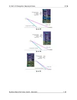
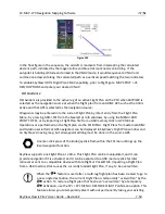
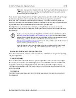
In a series of figures on the next page, the blue tick mark shown on the VSI represents the
vertical speed necessary to descend along a path calculated at the defined angle and arriving at
the intended destination point. Note, however, this indicator is a “future value
,
” giving the pilot
advance notice of the vertical speed which will be necessary once the aircraft intersects that
calculated path at its current altitude and ground speed. If the pilot were to immediately start
descending at a VSI equal to the blue tick mark indication, the aircraft would descend well prior
to the intended point.
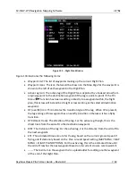
In contrast, the magenta line on the VSI indicates is a “current value” indicating the v
ertical
speed which will take the aircraft along a straight descent path from its current position to the
selected runway threshold (or specified height above).
If the aircraft maintains is current altitude until the magenta line descends to match the blue
tick mark, the aircraft will have intercepted the calculated descent path, similar to intercepting
a glideslope. If properly armed in the VNAV mode, the autopilot would sequence to that mode
and navigate down the calculated descent path.
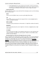
The following sequence of figures illustrates an aircraft’s approach to an airport, together with
screenshots of the vertical speed indicator showing both the magenta VS REQ’d r
eference line
and the blue calculated descent path indicator. Note that the vertical speed markers will not
show when navigating to an externally provided glide slope.

